5.
It is recommended that service valves be installed on the STS system inlet
and outlet so that the unit can be isolated for any maintenance or repairs
when necessary.
6.
All LAKOS STS systems are configured for either Source (S) or City (C)
backwash. If your system is designed for City (C) backwash, city (or other
external) water supply piping will need to be plumbed to the system
backwash inlet connection (see drawing STS-0002).
The pressure from this
external source must not exceed 30 PSI and may require that a pressure
regulator be installed (supplied by others).
7.
Backwash connection piping is not supplied by LAKOS and must be
provided on-site. Do not reduce the line size any smaller than the backwash
outlet pipe size. A backwash throttling valve (by others) should always be
installed in the piping to control backwash flow. Check local codes to
determine if appropriate backflow prevention is necessary on the backwash
line.
8.
Determine if the drain for the backwash can handle the necessary backwash
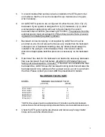
flow (see backwash flow chart below).
All LAKOS STS Media Filters are
factory set to backwash for 3 minutes**
. If the drain can not handle the total
backwash flow, LAKOS does offer backwash holding tanks that will allow the
backwash water to be siphoned off at a slower rate so as not to overwhelm
the drain. Please contact you local LAKOS representative for details.
BACKWASH FLOW CHART
MODEL
MINIMUM BACKWASH FLOW
(US GPM)
(M3/HR)
STS-15-025
18
4
STS-18-045
27
6
STS-24-075
47
11
STS-30-110
74
17
STS-36-165
106
24
STS-48-310
188
43
**NOTE: Flow values should be multiplied times “3” minutes to get the total backwash
gallons of water that will be purge during a standard factory recommended backwash cycle
9.
Check the STS system pump pre-strainer and remove any foreign matter.
Close and secure the strainer cover.
5


