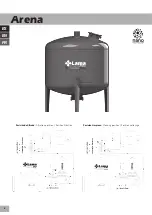
Funcionamiento
El sistema elegido es de los más fiables del mercado y le propor-
ciona la mejor calidad de filtración. Los elementos se suministran
generalmente desmontados para un fácil transporte, por lo que
deben ser conectados.
1.- Instale los filtros sobre una superficie plana
, según el plano
de montaje suministrado, a las distancias aproximadas. Coloque
los colectores de entrada y salida, abroche las bridas con sus jun-
tas, verifique que están apretados por igual en cruz. Conecte las
tuberías de drenaje (no suministradas) y diríjalas al lugar de eva-
cuación con suficiente espacio y volumen. Conecte los cuellos de
cisne de entrada y salida (no suministrados).
2.-
Conecte los sensores al programador.
Conecte las salidas a
las estaciones y posteriormente a los solenoides mediante sus
bases.
3.- Abra las tapas de inspección superiores
de los filtros de Are-
na y llénelos de agua hasta la mitad. Vierta el material filtrante
(estándar arena volcánica, sílice, u otros), muy poco a poco, evi-
tando romper los elementos de retención. Vierta la cantidad míni-
ma necesaria de material filtrante, según modelo, que encontrará
sobre la etiqueta de control de calidad.
4.-
Conecte la electricidad.
Lea previamente el manual del progra-
mador. La presión diferencial recomendada es de 0’5 a 0’8 Kg/cm².
5.-
Compruebe
que los tornillos estén bien apretados y suminis-
tre al sistema presión poco a poco, vigilando posibles fugas. La
fuga de agua por los conductos de drenaje cesa cuando el sistema
alcanza 1Kg/cm² de presión.
6.-
Ejecute varios lavados
seguidos hasta eliminar las impurezas
o restos del material filtrante.
7.-
Haga funcionar el sistema
al caudal y presión adecuados y
verifique que la pérdida de carga es la indicada en las tablas.
8.-
Regulación de
tiempos recomendados:
- Una limpieza por tiempo cada
24 h.
- Con válvulas de
2” y 3”, entre 1 y 3 min.
- Con válvulas de
4”, entre 2 y 4 min.
- Con doble válvula de
3” y 4”
,
consultar.
9.-
El
periodo de renovación del material filtrante
variará depen-
diendo del contaminante. Deje siempre el filtro con agua en su
interior, evitar que se produzca una pasta dura que le impedirá el
buen funcionamiento del mismo.
10.-
Después de una larga parada
, verifique que el material fil-
trante esté totalmente suelto, metiendo la mano por las tapas de
registro superiores. Si está compactado, sustitúyalo sacándolo
por la boca inferior. Ayúdese con agua y nunca golpee el interior,
pues los elementos plásticos internos se pueden romper.
11.-
Las
presiones de trabajo
de este equipo se han comproba-
do a
23ºC
en condiciones estándar. No se recomienda el uso del
equipo en temperaturas extremas, en caso de duda consulte con
su distribuidor.
12.-
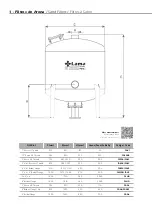
Los datos más importante los puedes consultar en el cuadro
de la
pag. 3.
1 - Filtros de Arena
/
Sand Filters /
Filtres à Sable
ES
9
Operation
The selected system is one of the most reliable on the market and
provides the best filtration quality. In general, the elements are
supplied disassembled for easy transport, so they must be con-
nected.
1.- Install the filters on a flat surface,
following the supplied as-
sembly drawing, at the approximate distances. Place the inlet and
outlet manifolds, fasten the flanges with their gaskets and check
that they are equally tightened crosswise. Connect the drain pipes
(not supplied in the standard configuration) and run them to an
evacuation location that has sufficient space and volume. Con-
nect the input and output goosenecks (not supplied in the stan-
dard configuration).
2.-
Connect the sensors to the programmer.
Connect the outputs
to the stations and then to the solenoids through their bases.
3.-
Open the sand filter top
inspection covers and fill them half full
of water. Pour in the filtering material (volcanic sand, silica, or other
material) gradually to avoid breaking the retention elements. Pour
in the minimum required quantity of filtering material, depending
on the model, which can be found on the quality control label.
4.-
Connect the electricity.
Read the programmer’s manual first.
The recommended differential pressure is 0.5 to 0.8 kg/cm².
5.-
Check
that the screws are tight and gradually fill the system
with pressure, watching for possible leaks. Water stops leaking
through the drain pipes when the system reaches a pressure of
1 kg/cm².
6.-
Run several washes
in a row to remove impurities or debris
from the filtering material.
7.-
Operate the system
at an adequate flow and pressure and
check that the pressure drop is as indicated on the tables.
EN


