background image


106 Bradrock Dr. Des Plaines, IL 60018-1967 

CPN 143459 

Instruction Drawing Number: P25-LDCC-1 

Tel: 847 299 1188 

Fax: 847 299 3061 


         Revision A00   Rev. Date: 09/20 

ECN:22665 


This manual is subject to change without notice. You may obtain the newest version of the manual at 

www.lamarchemfg.com


La Marche Manufacturing Company |www.lamarchemfg.com 

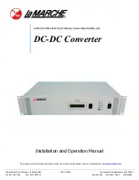
DC-DC Converter 


Installation and Operation Manual 

Summary of Contents for 143459

Page 1: ...Tel 847 299 1188 Fax 847 299 3061 Revision A00 Rev Date 09 20 ECN 22665 This manual is subject to change without notice You may obtain the newest version of the manual at www lamarchemfg com La Marche Manufacturing Company www lamarchemfg com DC DC Converter Installation and Operation Manual ...

Page 2: ...e sure that neither liquids nor any wet material come in contact with any internal components Do not operate this unit outside the input and output ratings listed on the unit nameplate Do not use this unit for any purpose not described in the operation manual Mechanical Safety This unit or parts of the unit may get very hot during normal operation use care when working nearby Do not expose equipme...

Page 3: ...erter sent back for evaluation and repair CAUTION Failure to properly file a claim for shipping damages or provide a copy of the claim to La Marche may void warranty service for any physical damages reported for repair Returns for Service Save the original shipping container If the product needs to be returned for service it should be packaged in its original shipping container If the original con...

Page 4: ...e 3 3 2 Front Panel Switch LED and Alarm Details 3 3 3 Rear Panel Details 4 3 4 Parallel Operation 5 4 0 Troubleshoot 5 Appendix A Technical Specifications 6 Appendix B Power Cabling Guide 7 Appendix C Manufacturer s Warranty 8 Appendix D Document Control and Revision History 9 Table of Figures Figure 1 DC DC Converter Overview 1 Figure 2 Rack Mounting Dimensions 2 Figure 3 DC Input and DC Output ...

Page 5: ......

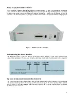
Page 6: ... 1 DC DC Converter Overview Understanding the Model Number The DCC model number is coded to describe the features that are included Find the model number on the nomenclature nameplate of the enclosure Follow the chart below to determine the configuration of the converter Optional Accessories Included in the Converter This inverter may have been outfitted with several optional accessories or option...

Page 7: ...pment in a location with corrosive gases e g over flooded Lead Acid batteries and dust The DCC utilizes fan assisted cooling so clearance of at least 6 inches of free air must be maintained in front and on top for proper cooling Maintain 12 inches 300 mm or more of clearance at the rear of the converter when rack mounting to allow for operation and maintenance The preferred fastener is a machine b...

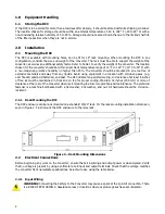
Page 8: ... comes with Bulk DC output connections at the rear of the Converter Connect DC cables to the equipment per the Figure 3 Select the recommended DC wire size using Table 4 Figure 3 DC Input and DC Output Connections to the DCC 3 0 Operation 3 1 Start Up Sequence After all DC input and output connections have been made apply DC power and turn on the converter Power Switch The unit will automatically ...

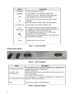
Page 9: ...t charge and Equal charge Turn to the right is Equal charge Turn to the left is float charge B Switch Manual and automatic Turn to the right is automatic Turn to the left is Manual Note Automatic float equal charge must be compatible with the power monitoring system Power Switch ON OFF of the dc converter Name Description DC Voltage input terminal Connect Red wire to terminal and Black wire to ter...

Page 10: ... following LED status RUN LED with Green color and ALM LED with RED color Load short circuit or overload Power off then eliminate short circuit or reduce load Restart again Output failure with the following LED status RUN LED with Green color and ALM LED with OFF Higher or lower DC Input voltage Adjust DC Input voltage to normal Range Other problems please contact the service department of La Marc...

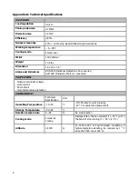
Page 11: ... LED Indicates Fault in a converter PROTECTION Output over under voltage Over current Short circuit Over temperature protection ENVIRONMENT Technical Specification Unit Operating Temperature 10 50 10 Module to work properly 20 C module rated power start Storage Temperature 40 85 Relative temperature 5 95 No condensation Cooling mode Forced air cooling Intelligent fan The fan will start if 55 5 the...

Page 12: ... loop feet MaxAmp Maximum allowable amperes for given voltage drop AVD Allowable voltage drop K 11 1 for commercial TW copper wire 17 4 for aluminum Calculating Wire Size Requirements AVD K LF A CMA Table 4 Wire Size Area Table Calculating Current Carrying Capacity of Wire K LF AVD CMA MaxAmp Size AWG Area CIR MILS Size MCM Area CIR MILS 18 1620 250 250000 16 2580 300 300000 14 4110 350 350000 12 ...

Page 13: ...ation adjustments and service arrangements Should minor adjustments be required the local La Marche Sales Representative should be contacted to provide this service All sales are final Only standard La Marche units will be considered for return A 25 restocking fee is charged when return is a factory authorized Special units are not returnable In no event shall La Marche Manufacturing Co have any l...

Page 14: ...9 Appendix D Document Control and Revision History Part Number 143459 Instruction Number P25 LDCC 1 Issue ECN ...

Reviews: