13
2.5
External Temperature Compensation (Option 11W/11Y)
The natural voltage of a battery changes as a function of temperature change. As the battery temperature rises,
the effective voltage of the battery decreases. Without Temperature Compensation, the battery charger will
always produce a set constant output voltage. As the battery temperature increases, this constant voltage will
then induce a higher output current from the charger. This higher current can result in overcharging the battery,
which in turn can result in damage to the batteries.
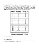
The TPSD2 temperature compensation rate can easily be adjusted in the menu from the default setting OFF to
1mV/°C/cell, up to 4mV/°C/cell. The temperature compensation considers 25°C as the nominal ambient
temperature and adjusts the voltage level based on the difference between the actual temperature and 25°C.
The battery manufacturer should be consulted for the proper temperature compensation slope, as well as the
Float and Equalize voltage set points.
An internal temperature probe is standard and will compensate for overall ambient temperature changes if the
batteries and charger are in the same room. The accuracy of temperature compensated charging can be greatly
enhanced by using an optional remote temperature probe directly on the battery (Option 11W/11Y). Option 11W
includes a 24-foot long temperature probe and Option 11Y includes a 100-foot long temperature probe. With
either option, approximately two feet of the probe is taken inside the charger enclosure.
External Temperature Probe Connection Procedure
Before making any connections to the A36D, ensure that the AC power is off at the main breaker box and the
charger’s breakers are off. Verify that no voltage is present by using a voltmeter at all input and output terminals.
NOTE:
Procedure only applies on A36D chargers with Option 11W/11Y.
1.
Locate the
TS-6
terminal strip inside the charger.
2.
Connect wire marked
F
to terminal
1
and wire marked
G
to terminal
2
. Refer to the figure below.
3.
Connect the black lead of the external probe to the other end of terminal
1
, and the red lead to the other
end of terminal
2
.
4.
Place the external probe in a desired location (it is recommended that the battery manufacturer be consulted
for placement of the probe).
Figure 10 –
Temperature Compensation Connection
(External and Internal)

