INSTALLATION AND OPERATING INSTRUCTIONS FOR MODEL A40/STANDARD - A40F/FILTERED
5 OF 12
A40/A40F
The La Marche Constavolt Rectifier is designed to operate on a specific type battery with a specific
number of cells. The nameplate on the charger indicates type and the number of cells required. Once
properly installed the rectifier should maintain the battery in a fully charged condition. Bolt the rectifier
to a sound structural member and mount such that the flow of air through the ventilators is not
obstructed. Binding posts with lug connectors are provided on a terminal board within the unit. When
hooking up the DC output cables to the battery, be certain the positive terminal of the charger is
connected to the positive battery terminal and the negative terminal is connected to the negative of the
battery. Before hooking up the AC input cable, check the line power with that specified on the unit
nameplate. A grounding connection is also provided for complete protection. All wiring to and from the
Constavolt should be in accordance with the local electrical requirements. The unit should not be
installed directly over flooded batteries.
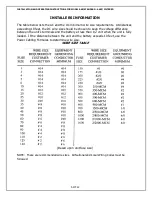
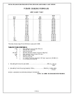
Input and output wiring may be connected to wire lugs, provided on the input and output terminals. The
tool used to secure the wire to the lug is T & B Sta-Kon WT-130A (lugs 10 through 18), and WT-115
(lugs 3 through 8).
To operate the charger, it is only necessary to plug in the AC power. The charger will automatically start
to charge the battery at some rate up to its maximum capacity depending upon the state of charge of
the battery and charge the battery to full charge and shutdown to a trickle charge-preserving-charge.
The Constavolt has current limiting characteristics such that the unit will not exceed approximately 125%
of its maximum output rating. The output is further protected by fuses for short circuiting conditions.
The output is automatically regulated such that line voltage variations of plus (+) or minus (-) 10% of
the nominal rating does not effect the operation of the Constavolt. The Constavolt will also operate on
very low input voltages, however, the maximum charge rate will be decreased.
By using transistors and diodes, etc., instead of electronic tubes and mechanical timers, the Constavolt is
designed to be virtually trouble and maintenance free. Automatic regulation is accomplished with a
saturable reactor regulator which, again, has no moving parts and requires no adjustments.
The charge is factory tested and pre-set so that no field adjustments are necessary. If filed adjustments
must be made, the taper and shutdown point may be adjusted. This adjustment may be made by
moving the red slider band on the voltage reference variable resistor RVI.
Moving this slider band toward the series connected resistor RV2 raises the shutdown point which allows
the battery voltage to rise to a higher point before shutting down to a trickle charge. Moving the red
slider band away from the series connected RV2 lowers the shutdown point.
It should not be necessary to make any adjustments to this charger and should any adjustments be
necessary extreme care should be taken in making the adjustment. An accurate DC voltmeter should be
used and the DC voltage at the charger and battery terminals should be measured. The battery voltage
should not exceed the battery manufacturer specifications. Settings above this point may cause
excessive (gassing) use of water and battery heating.
The Model A40F is similar to the Model A40, except it's output is filtered. It can be used with all types of
batteries, sealed maintenance free, valve regulated lead acid (VRLA) or standard flooded types.
WHEN ORDERING REPLACEMENT PARTS, SCHEMATICS OR REQUESTING SERVICE
INFORMATION, ALWAYS GIVE MODEL NUMBER, SERIAL NUMBER AND AC INPUT VOLTAGE.
CAUTION: THE Model A40 is NOT recommended for use on sealed batteries.


