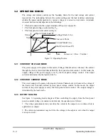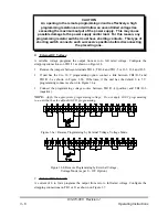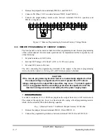
The leads to the remote meters should be twisted, and if strong AC or RF fields are present,
the lead should be shielded. One end of the shield should be grounded to terminal TB1/J1-14
and the other end left floating.
3.9 REMOTE SENSING (P.S. WITH OUTPUT VOLTAGE 300V OR
LESS)
In applications where the effect of the voltage drop (IR drop) of the load wires would
adversely affect the performance of the load. It is possible to sense the voltage at the load
rather than at the output terminals of the power supply. Remote sensing will therefore
remove the effect of changes in load current through the power distribution system. The
maximum available load voltage then equals the rated power supply output voltage less the
total of the IR drop.
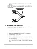
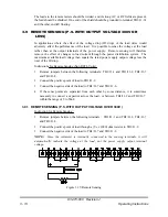
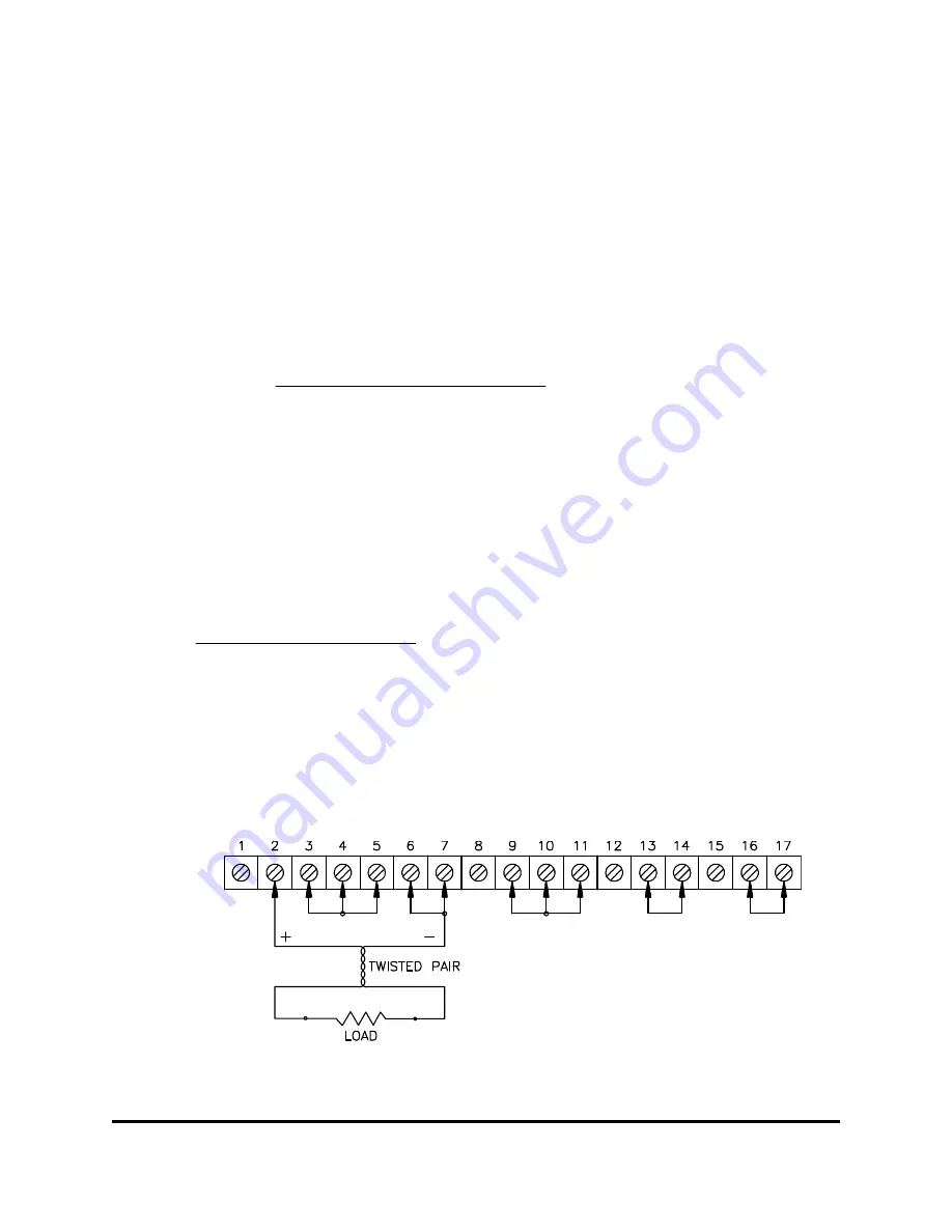
Instructions for Remote Sensing (Non RSTL Units):
1. Remove jumpers between the following terminals: TB1/J1-1 and TB1/J1-2, TB1/J1-7
and TB1/J1-8.
2. Connect the positive point of load to TB1/J1-2.
3. Connect the negative side of the load to TB1/J1-7 and TB1/J1-6.
4. If the sense points are separated from each other by some distance, it is sometimes
necessary to connect a capacitor across the load, or between TB1/J1-2 and TB1/J1-7,
within the range of 5 to 50uF.
3.9.1 REMOTE SENSING (P.S. WITH OUTPUT VOLTAGE OVER 300V )
Instruction for Remote Sensing :
1. Remove jumpers between the following terminals : TB1/J1-1 and TB1/J1-2, TB1/J1-7
and TB1/J1-8.
2. Connect the positive point of load through a (V
O
x 1000) ohm resistor to TB1/J1-2.
3. Connect the negative side of the load to TB1/J1-7 and TB1/J1-6
NOTE:
Since the voltmeter is internally connected to the sensing terminals, it will
automatically indicate the voltage at the load, not the power supply output terminal
voltage.
Figure 3.15: Remote Sensing
83-473-000 Revision J
3 - 13
Operating Instructions


