5 CALIBRATION AND TROUBLESHOOTING
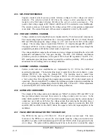
5.1 INTRODUCTION
A regularly scheduled maintenance of once a year is recommended for the EMS series power
supply. As a minimum, maintenance should consist of a thorough cleaning of the interior,
and a visual inspection of the fans and components on the printed circuit boards.
NOTE:
Maintenance and/or calibration procedures contained in this section will not void
the unit warranty.
CAUTION
Hazardous voltages are present during normal operation. Before removing the
cover, the power source should be disconnected, and a period of 20 minutes
allowed for the discharge of storage capacitance. Refer to Safety Precautions.
5.2 INSPECTION AND CLEANING
1. Clean exterior with a clean dry cloth.
2. Remove screws from all sides of cover and remove cover.
3. Check for loose wires, burn marks, etc.
4. Remove dust from parts (fans) with a small, long bristled brush or use an air blower to
remove the dust.
5.3 CALIBRATION
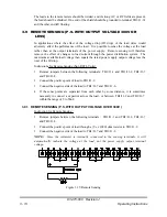
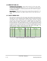
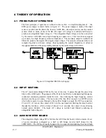
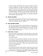
The calibration procedure that follows applies to a properly functioning unit. Any
malfunction must be corrected before proceeding with calibration. It is necessary only to
remove the top cover to make these calibrations. The following equipment is required for
calibration :
1. Digital voltage Multimeter.
2. Adjusting screw driver.
3. Jumper capable of handling the maximum output current of the power supply.
5.3.1 Analog Meter Zero Calibration
The zero set for both voltage and current front panel analog meters is located on the panel
meters and is accessible at the front panel. Zero adjust should be performed with power
removed. For power supplies with analog meters this calibration should be performed before
83-473-000 Revision J
5 - 1
Calibration and Troubleshooting

