5.4 TROUBLESHOOTING
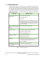
Using this section in conjunction with section IV and the schematics that are provided in this
manual, will help tremendously in troubleshooting the power supply by isolating and locating
the cause of the fault. Before attempting to troubleshoot the power supply, perform Section
2.4 to determine whether the fault is with the associated circuitry or with the power supply.
If the supply fails the Electrical Inspection test, check for appropriate link connections at
TB1/J1 (refer to Section 3). The following table provides a listing of the most common
symptoms and their causes.
a)
Links on TB1/J1 are disconnected.
b)
Voltage or Current control is disconnected or defective.
Output goes high (activating
OVP). Voltage and/or current
is not adjustable.
a)
Check load connections. Especially on high current
units, load connections should be very tight.
b)
Fan(s) are defective.
Overheating
a)
Output capacitor(s) defective.
b)
Feedback channel unstable.
Oscillates/ High Ripple
a)
Input diode bridge(s) CR1 (CR2,CR3) shorted.
b)
Transistors on A200 Bd. shorted.
c)
Output diode Bridge(s) shorted.
Circuit breaker trips
a)
OVP Adjust rotated counterclockwise.
Low or no output voltage or
output current with OVP LED
glowing
a)
Front panel meter is defective.
b)
Check input voltage.
c)
Fuse blown
d)
A100 Bd. Check for voltage at cathode of CR15 with
respect to pin 7 of TB1/J1. If low (< 4V) check which of
the following diodes is turned on: CR12 remote turn on,
CR13A (undervoltage, CR14 thermostat, CR16 OVP
and CR17 soft start.
Low or no output voltage or
output current
PROBABLE CAUSE
SYMPTOM
Table 5.1: Troubleshooting Guide
83-473-000 Revision J
5 - 3
Calibration and Troubleshooting


