background image

LAMBDA EMI

405 ESSEX ROAD, NEPTUNE, NJ  07753

TEL:  (732) 922-9300

FAX:  (732) 922-9334

INSTRUCTION MANUAL FOR

83-475-001  Revision D

MODEL                                                

SERIAL NUMBER                               

Summary of Contents for ESKI

Page 1: ...LAMBDA EMI 405 ESSEX ROAD NEPTUNE NJ 07753 TEL 732 922 9300 FAX 732 922 9334 INSTRUCTION MANUAL FOR 83 475 001 Revision D MODEL SERIAL NUMBER...

Page 2: ...3 SIGNAL FLOW SCHEMATIC 01 000 225 13 4 2 POWER FLOW SCHEMATIC 01 475 005 13 4 1 GENERAL 13 4 PRINCIPLES OF OPERATION 7 3 2 MODES OF OPERATION 7 3 1 TURN ON CHECK OUT PROCEDURE 6 3 OPERATING INSTRUCTI...

Page 3: ...power supply reliability Ideally when power supplies are mounted in a rack the rack should have no sides or rear covers Since this is usually not practical or safe the installer must consider the effe...

Page 4: ...phase 47 63 Hz AC INPUT SINGLE PHASE UNIT 208 220 VAC 10 Single Phase 47 63 Hz AC INPUT CURRENT THREE PHASE UNIT 22 Amps per phase for 3 phase power AC INPUT CURRENT SINGLE PHASE UNIT 45 Amps REGULATI...

Page 5: ...primary circuit protection with on off control Current adjustment is via a single 10 turn potentiometer located on the front panel Indication of the output current is provided by an ammeter mounted on...

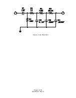
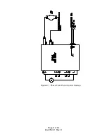
Page 6: ...Figure 1 Loss Pass Filter Page 4 of 18 83 475 001 Rev D...

Page 7: ...e size should be at least 10 gauge The current input for single phase is rated for 50 Amps and the wire size should be at least 8 gauge The connecting wire size is larger than service rating 2 4 COOLI...

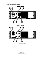
Page 8: ...3 OPERATING INSTRUCTIONS Figure 2 Front Panels Page 6 of 18 83 475 001 Rev D...

Page 9: ...output will occur This is caused by the soft start circuit 3 1 5 The UNIT ON INDICATOR 2 should be on Turn LAMP ON OFF SWITCH 3 on 3 1 6 Advance CURRENT CONTROL 5 slowly The DC VOLTMETER 7 will defle...

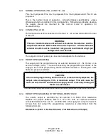
Page 10: ...nal 3 2 3 REMOTE PROGRAMMING This supply can be programmed by an external resistance 0 5k Ohms or an external voltage 0 5V The wire connecting the programming terminals of the supply to the remote pro...

Page 11: ...Figure 3 1 Phase Front Panel Control Hookup Page 9 of 18 83 475 001 Rev D...

Page 12: ...on until the external interlock circuit is closed The current and voltage is less than 25 mA and 15 volts The interlock should be connected between Pins 3 10 of P1 When these two Pins are open the pow...

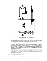
Page 13: ...ored by reading the voltage between Pins 4 2 of P1 This voltage is set for 1 volt 10 Amps when received from the factory and can be loaded with a resistance of 10k Ohms Figure 4 3 Phase External Contr...

Page 14: ...Figure 4A 1 Phase External Control Hookup Page 12 of 18 83 475 001 Rev D...

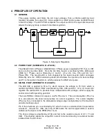
Page 15: ...which produces the 25kV start pulse 4 3 SIGNAL FLOW SCHEMATIC 01 000 225 The 208 VAC is applied to T3 T4 which reduces the voltage to 15 VAC which is rectified by CR45 CR49 CR47 and filtered by C33 C3...

Page 16: ...interlock circuit is made up of CR12 13 and P1 Pins 1 9 3 and 10 When these pins are shorted the input bias to Q1 is disabled allowing the PWM to operate The over current detector U4A monitors the vo...

Page 17: ...Ohm resistor before any contact with the circuit 5 3 CALIBRATION This procedure applies to the adjustment and calibration of a properly functioning unit only Any malfunction must be corrected before...

Page 18: ...5 3 3 FULL SCALE CURRENT OUTPUT 1 Repeat steps 1 2 and 3 as in paragraph 5 3 1 2 Turn on the front panel current control full CCW 3 The output current should be zero if not adjust R160 for zero curre...

Page 19: ...he front panel control If not check P1 jumpering Q103 U105B and CR122 4 Check voltage between TP111 and TP115 It should be proportional to the 0 to 5 volts of step 3 If not check U110B T102 U106 and U...

Page 20: ...020 Op Amp U101 3 4 5 U109 10 UC3901 64 003 043 IC U106 U111 MOC3041 64 008 007 Opto Isolator U301 2N6348 63 002 001 TRIAC Q301 20 395 000 A100 PC Board A100 53 002 012 MOV 575 VAC TH3 53 002 002 MOV...

Reviews: