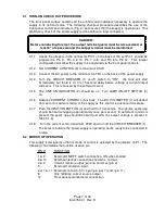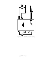
3.2.1 NORMAL OPERATION (FIG. 3 AND FIG. 3A)
Pins 1 & 9 jumpered, Pins 3 & 10 jumpered, Pins 7 & 8 jumpered and Pins 12 & 6
jumpered.
This is the normal mode of operation. All performance specifications, unless
otherwise stated, are defined in this configuration. Should any problems develop,
the supply should be returned to this normal mode of operation for
trouble-shooting.
3.2.2 CONNECTING LOAD
The lamp load must be connected to the two 1/4 - 20 screw terminals at the rear
of the unit.
WARNING:
This is a transformerless unit without an Isolation Transformer and the
output terminals are NOT isolated from the input line. All terminals and
external circuits must be insulated from ground to withstand a high pot
voltage of at least 30 kVdc.
The output terminals' polarity is silk-screened adjacent to the terminal.
3.2.3 REMOTE PROGRAMMING
This supply can be programmed by an external resistance (0 - 5k Ohms) or an
external voltage (0-5V). The wire connecting the programming terminals of the
supply to the remote programming device should be twisted, or if strong AC or RF
fields are present, shielded.
CAUTION:
If the remote programming function fails or is inadvertently adjusted, the
output current could go to 110% of maximum output. This will cause the
over-current circuit to shut down the supply until it is reset by turning off
the AC circuit breaker.
3.2.4 REMOTE PROGRAMMING BY EXTERNAL RESISTANCE
The current output is controlled by an external 0 to 5000 Ohm resistance.
Replace the jumper between Pins 6 & 12 of P1 with an external resistance
connected between Pins 6 & 11. At 5000 Ohms the supply will output full current.
At less than full output the programming resistance is determined from the
following formula:
Resistance = (5000 X Desired Current / Full Rated Current Output)
Page 8 of 18
83-475-001 Rev. D
Summary of Contents for ESKI
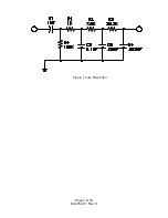
Page 6: ...Figure 1 Loss Pass Filter Page 4 of 18 83 475 001 Rev D...
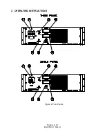
Page 8: ...3 OPERATING INSTRUCTIONS Figure 2 Front Panels Page 6 of 18 83 475 001 Rev D...
Page 11: ...Figure 3 1 Phase Front Panel Control Hookup Page 9 of 18 83 475 001 Rev D...
Page 14: ...Figure 4A 1 Phase External Control Hookup Page 12 of 18 83 475 001 Rev D...


