5 MAINTENANCE AND TROUBLESHOOTING
5.1 GENERAL
A regularly scheduled preventative maintenance consisting of a thorough cleaning of
interior and a visual inspection of the components on the circuit boards and heatsinks
mounted on the chassis floor. A relatively clean location would require at least one
inspection every six months.
5.2 INSPECTION AND CLEANING
CAUTION:
Always disconnect AC power from the supply before removing the cover.
5.2.1 Remove the (12) 6-32 screws from the covers.
5.2.2 Remove the wrap-around cover by lifting upward.
5.2.3 Check for loose wire connections, burn marks etc...
5.2.4 Remove dust from in and around parts with a small brush or compressed air.
5.2.5 Check the fan to be sure it operates freely and turns when power is applied.
CAUTION:
Whenever power is applied and removed, all capacitors should be
discharged through a 10 Ohm resistor before any contact with the circuit.
5.3 CALIBRATION
This procedure applies to the adjustment and calibration of a properly functioning unit
only. Any malfunction must be corrected before proceeding with calibration. Remove the
top cover to make these calibrations.
CAUTION:
DANGER LETHAL VOLTAGES
This Power Supply contains very lethal voltage and no work should be attempted unless
the person doing the work is a highly trained electronic technician who has studied the
schematics and understands how the circuit operates and takes safety measures to
prevent injury.
(Note the location of parts: the 100 numbers are on the A100 PCB, the
300 numbers are on the A300 board, etc...)
Equipment required:
1. Oscilloscope - Dual trace, 60 MHz, isolated from ground,
Philips PM3267 or equivalent.
2. Shunt - 50 Amp 100 mV Empro HA50-100
3. Multimeter -
Fluke 360 or equivalent.
4. Load - 6kW Resistive load 3.1 Ohm
Unless the power supply is found to be outside the normal tolerance, no adjustment
should be attempted.
5.3.1 CURRENT METER
Page 15 of 18
83-475-001 Rev. D
Summary of Contents for ESKI
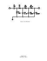
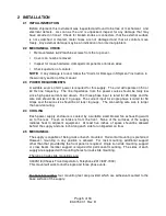
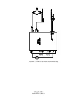
Page 6: ...Figure 1 Loss Pass Filter Page 4 of 18 83 475 001 Rev D...
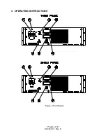
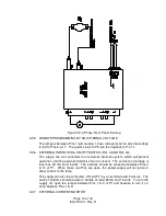
Page 8: ...3 OPERATING INSTRUCTIONS Figure 2 Front Panels Page 6 of 18 83 475 001 Rev D...
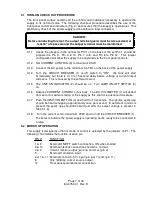
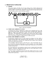
Page 11: ...Figure 3 1 Phase Front Panel Control Hookup Page 9 of 18 83 475 001 Rev D...
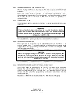
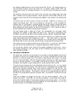
Page 14: ...Figure 4A 1 Phase External Control Hookup Page 12 of 18 83 475 001 Rev D...

