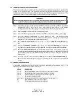
5.4 TROUBLESHOOTING
WARNING:
When servicing supply, dangerous voltage levels exist. Be especially careful of
personnel and equipment because this supply is not isolated from the AC line.
Almost all measurements will be made with one terminal connected to AC line
potential.
Most unit malfunctions will originate on the circuit card.
5.4.1 OVERALL TROUBLESHOOTING PROCEDURE
1. Check for obvious trouble such as input power failure, loose P1 or improper
jumpering.
2. Check the DC bias supplies.
a. 12 volts TP112-TP113
b. 15 volts TP114-TP115
c. 15 volts TP116-TP117
3. Check voltage between TP106 and TP113. This voltage should be adjustable
from 0 to 5 volts by the front panel control. If not, check P1 jumpering, Q103,
U105B and CR122.
4. Check voltage between TP111 and TP115. It should be proportional to
the 0 to 5 volts of step 3. If not, check U110B, T102, U106 and U105A.
5. Check voltage at the collector of Q104 (metal case) and TP115. It should be
above 12Vdc. If not, check the voltage at TP101, TP102, TP103, TP104,
anode CR112 and CR113 to TP113 to determine why Q104 is on.
6. Output not controllable. Check the following:
a. Pulses P104 (Pins 5 and 4) controllable by current control on front panel.
b. Pulses at U202 (Pin 7).
c. Pulses at junction of R209 & 210, R211 & 212 and R213 & 214.
d. Check Q201, Q202 and Q203.
7. IF Q201-Q203 have been changed, be careful to thoroughly clean the heatsink
and insulator. Then reapply a light coating of silicone heatsink compound.
Then evenly tighten the mounting screws.
Page 17 of 18
83-475-001 Rev. D
Summary of Contents for ESKI
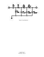
Page 6: ...Figure 1 Loss Pass Filter Page 4 of 18 83 475 001 Rev D...
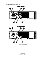
Page 8: ...3 OPERATING INSTRUCTIONS Figure 2 Front Panels Page 6 of 18 83 475 001 Rev D...
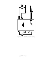
Page 11: ...Figure 3 1 Phase Front Panel Control Hookup Page 9 of 18 83 475 001 Rev D...
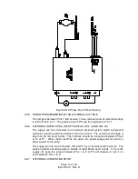
Page 14: ...Figure 4A 1 Phase External Control Hookup Page 12 of 18 83 475 001 Rev D...

