8
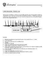
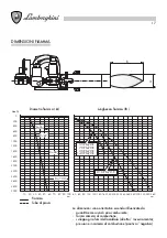
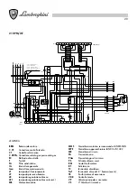
LEGENDA
1 Quadro con apparecchiatura
2 Corpo
3 Pressostato aria
4 G/elettrodi
5 Flangia attacco
6 Linea interna gas
7 Boccaglio
8 Motore
9 Ventola
10 Trasformatore
11
Servocomando aria
12
Valvola principale
13
Valvola sicurezza
14
Pressostato gas
4
5
6
7
3
10
8
2
9
1
11
14
13
12
I
∞
H
F
G
A
L
D
E
B
C
210 PM/2-E
2"
318
-
240
228
M14
460
200
155
470
800
1450
210 PM/2-E
2"
318
-
240
228
M14
460
200
155
470
800
1450
210 PM/2-E
DN 100
318
-
240
228
M14
460
200
155
470
860
1450
140 PM/2-E
1"1/2
283
-
210
197
M14
460
200
140
470
730
1350
140 PM/2-E
1"1/2
283
-
210
197
M14
460
200
140
470
730
1350
140 PM/2-E
2"
283
-
210
197
M14
460
200
140
470
750
1350
140 PM/2-E
DN 80
283
-
210
197
M14
460
200
140
470
840
1350
90 PM/2-E
DN 65
283
-
210
197
M14
460
200
140
470
730
1350
90 PM/2-E
1"1/2
283
-
210
197
M14
460
200
140
470
730
1350
90 PM/2-E
DN 65
283
-
210
197
M14
460
200
140
470
760
1350
70 PM/2-E
1"1/2
283
225
180
170
M14
400
140
120
470
730
1210
70 PM/2-E
2"
283
225
180
170
M14
400
140
120
470
750
1210
70 PM/2-E
DN 65
283
225
180
170
M14
400
140
120
470
750
1210
55 PM/2-E
1"1/4
283
225
180
170
M14
400
140
120
470
730
1210
55 PM/2-E
1"1/2
283
225
180
170
M14
400
140
120
470
730
1210
55 PM/2-E
DN 65
283
225
180
170
Ø
Ø
M14
400
140
max
min
max
min
120
470
730
1210
L
I
H
G
F
E
D
C
B
A
Modello
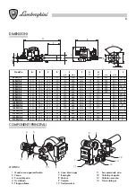
DIMENSIONI
COMPONENTI PRINCIPALI


