background image

AXE 3 D

15

EN

cod. 3540Z230  -  01/2011  (Rev. 00)

4.3 Maintenance

Periodical check

To ensure correct operation of the unit over time,  have qualified personnel carry out a
yearly check,  providing for the following:

The control and safety devices  must function correctly.

The fume exhaust circuit must be  perfectly efficient.

Check there are no obstructions or dents in the  fuel supply and return pipes.

Clean the filter of the fuel  suction line.

Measure the correct fuel consumption

Clean the combustion head in the  fuel outlet zone, on the swirl disc.

Leave the burner running at full rate for  approximately ten minutes, then analyse
the combustion,  checking:

-

All the  elements specified in this manual are set correctly

-

Temperatures of the fumes at the flue

-

CO2 percentage content

The air-fume end piece and ducts must be free of obstructions and leaks

The burner and exchanger must be  clean and free of deposits. For possible clean-
ing do not use chemical products or wire brushes.

The gas and water systems must be airtight.

The water pressure in the cold water system must be approx. 1 bar; otherwise, bring
it to that value.

The circulating pump must not be blocked.

The expansion tank must be filled.

Check the magnesium anode and replace it if necessary.

A

The boiler casing, control panel and  aesthetic parts can be cleaned with a  soft
and damp cloth, if necessary soaked in soapy water. Do not use any abrasive
detergents and solvents.

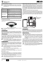
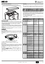
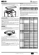
Boiler cleaning

1.

Disconnect the power supply to the boiler.

2.

Remove the front top and bottom panel.

3.

Open the door by undoing the knobs.

4.

Clean the inside of the boiler and the entire path of exhaust fumes, using a tube
brush or compressed air.

5.

Then close the door, securing it with the knob.

To clean the burner, refer to the Manufacturer's instructions.

4.4 Troubleshooting

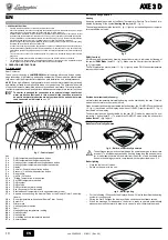
Diagnostics

The boiler is equipped with an advanced self-diagnosis system. In case of a boiler anom-
aly, the display will flash together with the fault symbol (detail 22 - fig. 1) indicating the
fault code. 

There are faults that cause permanent shutdown (marked with the letter “

A

”): to restore

operation press the RESET button (detail 8 - fig. 1) for 1 second or RESET on the op-
tional remote timer control if installed; if the boiler fails to start, it is necessary to eliminate
the fault indicated by the operation LEDs.

Other faults (marked with the letter “

F

”) cause temporary shutdowns that are automati-

cally reset as soon as the value returns within the boiler's normal working range.

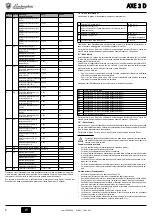
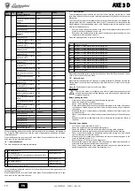
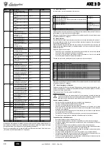
Table. 2 - Fault list

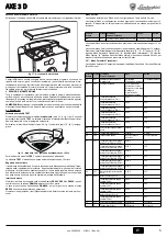
5. TECHNICAL DATA AND CHARACTERISTICS

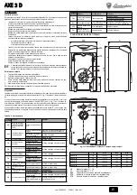
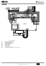
5.1 Dimensions, connections and main components

fig. 19 - Dimensions, connections and main components

10

System delivery 1" 1/2"

11

System return 1" 1/2"

246

Heating system pressure transducer

275

Heating system drain cock

278

Double sensor ( heating)

Fault
code

Fault

Possible cause

Cure

A01

Burner shutdown
(RESET ONLY OCCURS 
ON THE BURNER)

Refer to the burner manual

A03

Overtemperature protec-
tion activation

Heating sensor damaged

Check the correct positioning and operation of 
the heating sensor

No water circulation in the 
system

Check the circulating pump

Air in the system

Vent the system

F07

Wiring fault

Connector X5 not connected Check the wiring

F10

Delivery sensor 1 fault

Sensor damaged

Check the wiring or replace the sensor

Wiring shorted
Wiring disconnected

F11

DHW sensor fault

Sensor damaged

Check the wiring or replace the sensor

Wiring shorted
Wiring disconnected

F13

Wiring fault

Connector X12 not con-
nected

Check the wiring

F14

Delivery sensor 2 fault

Sensor damaged

Check the wiring or replace the sensor

Wiring shorted
Wiring disconnected

F34

Supply voltage under 
170V.

Electric mains trouble

Check the electrical system

F35

Mains frequency fault

Electric mains trouble

Check the electrical system

F37

Incorrect system water 
pressure

Pressure too low

Fill the system

Sensor damaged

Check the sensor

F39

External probe fault

Probe damaged or wiring 
shorted

Check the wiring or replace the sensor

Probe disconnected after 
activating the sliding temper-
ature

Reconnect the external probe or disable the 
sliding temperature

F40

Incorrect system water 
pressure

Pressure too high

Check the system
Check the safety valve
Check the expansion tank

A41

Sensor positioning

Delivery sensor not inserted 
in boiler shell

Check the correct positioning and operation of 
the heating sensor

F42

Heating sensor fault

Sensor damaged

Replace the sensor

F47

System water pressure 
sensor fault

Wiring disconnected

Check the wiring

A

Ø a4

Ø a5

Ø a6

AXE 3 D 32

400

120-130

105

150

AXE 3 D 45

500

120-130

105

150

AXE 3 D 59

600

120-130

105

150

AXE 3 D 74

700

120-130

105

150

AXE 3 D 90

830

120-130

125

170

Fault
code

Fault

Possible cause

Cure

268

500

850

A

553

65

71

1

a4

10

11

275

a5

a6

246

278

Summary of Contents for AXE3D 32

Page 1: ...USO L INSTALLAZIONE E LA MANUTENZIONE EN INSTRUCTIONS FOR USE INSTALLATION AND MAINTENANCE FR INSTRUCTIONS D UTILISATION D INSTALLATION ET D ENTRETIEN ES INSTRUCCIONESDEUSO INSTALACI NYMANTENIMIENTO...

Page 2: ...lda sanitaria 3 Tasto decremento impostazione temperatura impianto riscaldamento 4 Tasto incremento impostazione temperatura impianto riscaldamento 5 Display 6 Tasto selezione modalit Estate Inverno 7...

Page 3: ...aldaia lavora con Temperatura Scorrevole In questa modalit la temperatura dell impianto di riscaldamento viene regolata a seconda delle condizioni climatiche esterne in modo da garantire un elevato co...

Page 4: ...ra si renda necessario consentito l uso di liquidi antigelo additivi e inibitori solo ed esclusivamente se il produttore di suddetti liquidi o additivi fornisce una garanzia che assicuri che i suoi pr...

Page 5: ...al Men di configurazione avviene premendo i tasti sanitario insieme per 10 secondi E disponibile un solo parametro modificabile solo da scheda per questioni di sicurezza L uscita dal Men di configuraz...

Page 6: ...e della caldaia effettuando diverse prove di accensione e spe gnimento per mezzo del termostato ambiente o del comando remoto Assicurarsi che il consumo del combustibile indicato al contatore corrispo...

Page 7: ...olvere l anomalia che viene indicata nei leds di funzionamento Altre anomalie causano blocchi temporanei contraddistinte con la lettera F che vengono ripri stinati automaticamente non appena il valore...

Page 8: ...3 94 5 Classe efficienza direttiva 92 42 EEC Pressione max esercizio riscaldamento bar 6 6 6 6 6 PMS Pressione min esercizio riscaldamento bar 0 8 0 8 0 8 0 8 0 8 Temperatura max riscaldamento C 95 9...

Page 9: ...te opzionale 130 Circolatore sanitario opzionale 138 Sonda esterna opzionale 139 Unit ambiente opzionale 211 Connettore bruciatore 246 Trasduttore di pressione 278 Sensore doppio riscaldamento sicurez...

Page 10: ...rature setting increase button 3 Heating system temperature setting decrease button 4 Heating system temperature setting increase button 5 Display 6 Summer Winter mode selection button 7 Economy Comfo...

Page 11: ...perature In this mode the heating system temperature is controlled according to the outside weather conditions in order to ensure high comfort and energy efficiency during the entire period of the yea...

Page 12: ...if the manufacturer of these fluids or additives guarantees they are suitable for this use and cause no damage to the heat exchanger or other components and or materials of the boiler unit and sys te...

Page 13: ...lable To exit the configuration Menu press the DHW buttons together for 10 seconds The card Service Menu is accessed by pressing the Reset button for 10 seconds Press the Heating buttons to select tS...

Page 14: ...us tests turning it on and off with the room thermostat or remote control Make sure the fuel consumption indicated on the meter matches that given in the technical data table on sec 5 3 Ensure the sea...

Page 15: ...the fault indicated by the operation LEDs Other faults marked with the letter F cause temporary shutdowns that are automati cally reset as soon as the value returns within the boiler s normal working...

Page 16: ...94 3 94 1 94 94 3 94 5 Efficiency class Directive 92 42 EEC Max working pressure in heating bar 6 6 6 6 6 PMS Min working pressure in heating bar 0 8 0 8 0 8 0 8 0 8 Max heating temperature C 95 95 9...

Page 17: ...stat optional 130 DHW circulating pump optional 138 External probe optional 139 Room unit optional 211 Burner connector 246 Pressure transducer 278 Double sensor heating safety 304 2nd stage burner co...

Page 18: ...Touche pour diminuer le r glage de la temp rature de l installation de chauffa ge 4 Touche pour augmenter le r glage de la temp rature de l installation de chauf fage 5 Afficheur 6 Touche de s lection...

Page 19: ...yst me de r gulation de la chaudi re travaille en mode temp rature volutive Dans ce mode la temp rature de l installation chauffage est r gul e en fonction des condi tions climatiques ext rieures de m...

Page 20: ...s additifs et des inhi biteurs seulement et exclusivement si le producteur de ces liquides ou additifs fournit une garantie qui assure que ses produits sont idoines l utilisation et ne provoquent pas...

Page 21: ...vice Pour acc der au menu Configuration appuyer simultan ment 10 secondes sur les tou ches Sanitaire Un seul param tre disponible peut tre modifi uniquement partir de la carte pour des raisons de s cu...

Page 22: ...thermostat d ambiance et de la commande distance S assurer que la consommation de combustible indiqu e par le compteur corresponde celle qui est indiqu e sur le tableau des caract ristiques techniques...

Page 23: ...qui est signal par les LED de fonctionnement Les autres anomalies qui causent un blocage momentan de la chaudi re sont indi qu es l aide de la lettre F ces anomalies sont automatiquement limin es d s...

Page 24: ...0 94 3 94 1 94 94 3 94 5 Classe de rendement selon la directive 92 42 EEC Pression maxi de service chauffage bar 6 6 6 6 6 PMS Pression mini de service chauffage bar 0 8 0 8 0 8 0 8 0 8 Temp rature ma...

Page 25: ...ambiance option 130 Circulateur eau chaude sanitaire option 138 Sonde ext rieure option 139 Unit ambiante option 211 Connecteur br leur 246 Transducteur de pression 278 Capteur double chauffage s curi...

Page 26: ...ecla para seleccionar el modo Economy Comfort 8 Tecla de rearme reset 9 Tecla para encender apagar el equipo 10 Tecla men Temperatura adaptable 11 Indicaci n de que se ha alcanzado la temperatura prog...

Page 27: ...funciona con Temperatura adaptable En esta modalidad la temperatura del circuito de calefacci n se regula en funci n de las condiciones clim ticas exteriores con el fin de garantizar mayor confort y...

Page 28: ...vos e inhibidores a condi ci n de que el fabricante de dichos productos garantice que est n indicados para este uso y que no da an el intercambiador de la caldera ni ning n otro componente o material...

Page 29: ...sanitaria durante 10 segundos Por seguridad hay un solo par metro modificable nicamente desde la tar jeta Para salir del men Configuraci n pulsar las dos teclas del agua sanitaria durante 10 segundos...

Page 30: ...Comprobar que el consumo del combustible indicado en el contador corresponda al indica do en la tabla de datos t cnicos de la sec 5 3 Controlar la eficaz estanqueidad de la puerta del quemador y de la...

Page 31: ...al a indicada por los leds Las anomal as que se indican con la letra F causan bloqueos transitorios que se resuelven au tom ticamente apenas el valor vuelve al campo de funcionamiento normal de la cal...

Page 32: ...94 3 94 5 Clase de eficiencia seg n directiva 92 42 CE Presi n m xima funcionamiento calefac ci n bar 6 6 6 6 6 PMS Presi n m nima funcionamiento calefac ci n bar 0 8 0 8 0 8 0 8 0 8 Temperatura m xi...

Page 33: ...mbiente opcional 130 Bomba de circulaci n para AS opcional 138 Sonda exterior opcional 139 Unidad de ambiente opcional 211 Conector del quemador 246 Transductor de presi n 278 Sensor doble calefacci n...

Page 34: ...7 RXPS HSLORJ 9 OHLWRXUJ D9 Economy Comfort 8 RXPS RESET SDQDIRU 9 RXPS HQHUJRSR KVK9 DSHQHUJRSR KVK9 VXVNHX 9 10 RXPS PHQR 0HWDEOKW THUPRNUDV D 11 QGHL K HS WHX K9 HSLOHJP QK9 THUPRNUDV D9 HVWR QHUR...

Page 35: ...QDND FHLULVWKU ZQ OHSW 5 fig 1 HPIDQ HWDL K WU FRXVD H ZWHULN THUPRNUDV D SRX PH WU R H ZWHULN 9 DQLFQHXW 9 7R V VWKPD U TPLVK9 WRX O EKWD OHLWRXUJH PH PHWD EOKW THUPRNUDV D 6WK OHLWRXUJ D DXW K THUP...

Page 36: ...D GLD VIDO HL WL WD SUR QWD WRX H QDL NDW OOKOD JL DXW Q WK FU VK NDL GHQ SURNDOR Q EO EH9 VWRQ HQDOO NWK WRX O EKWD VH OOD H DUW PDWD NDL XOLN WRX O EKWD NDL WK9 HJNDW VWDVK9 SDJRUH HWDL K FU VK DQWL...

Page 37: ...DVK VWR PHQR GLDP UIZVK9 SU SHL QD SDW VHWH WDXW FURQD WD NRXPSL QHUR RLNLDN 9 FU VK9 JLD 10 GHXWHU OHSWD LDW THWDL P QR P D SDU PHWUR9 SRX PSR UH QD WURSRSRLKTH DS WKQ SODN WD JLD O JRX9 DVIDOH D9 LD...

Page 38: ...TPLVK9 QHUR RLNLDN 9 FU VK9 P02 2 55 65 C 65 C 0 JLVWR VKPH R U TPLVK9 QHUR RLNLDN 9 FU VK9 P02 3 0 JLVWR VKPH R U TPLVK9 QHUR RLNLDN 9 FU VK9 P02 4 0 JLVWR VKPH R U TPLVK9 QHUR RLNLDN 9 FU VK9 P02 5...

Page 39: ...H9 WK9 NDWDVNHXDVWLN 9 HWDLUH D9 4 4 S OXVK WZQ SUREOKP WZQ L JQZVK 2 O EKWD9 GLDT WHL SURKJP QR V VWKPD DXW PDWK9 GL JQZVK9 6H SHU SWZVK DQZPDO D9 VWR O EKWD K RT QK DQDERVE QHL SDU OOKOD PH WR V PER...

Page 40: ...0 94 3 94 1 94 94 3 94 5 DWKJRU D DS GRVK9 RGKJ D 92 42 2 0 J S HVK OHLWRXUJ D9 T UPDQVK9 bar 6 6 6 6 6 PMS O F S HVK OHLWRXUJ D9 T UPDQVK9 bar 0 8 0 8 0 8 0 8 0 8 0 J THUPRNUDV D T UPDQVK9 C 95 95 95...

Page 41: ...X SURDLUHWLN 130 XNORIRUKW 9 QHUR RLNLDN 9 FU VK9 SURDLUHWLN 138 ZWHULN 9 DQLFQHXW 9 SURDLUHWLN 139 0RQ GD F URX SURDLUHWLN 211 6XQGHW UD9 NDXVW UD 246 0HWDWURS D9 S HVK9 278 LSO 9 DLVTKW UD9 T UPDQVK...

Page 42: ...Tast pentru m rirea temperaturii apei calde menajere 3 Tast pentru mic orarea temperaturii din instala ia de nc lzire 4 Tast pentru m rirea temperaturii din instala ia de nc lzire 5 Afi aj 6 Tast sele...

Page 43: ...det 5 fig 1 se vede temperatura extern curent detectat de sond Sistemul de reglare al centralei lucreaz cu Temperatur variabil n acest mod temperatura din instala ia de nc lzire este reglat n func ie...

Page 44: ...respectivi ofer o garan ie care s asigure c produsele sale sunt corespunz toare i nu provoac defectarea schimb torului de c ldur al centralei sau a altor componente i sau materiale din central i din i...

Page 45: ...de 10 secunde Este disponibil un singur parametru care poate fi modificat doar de la cartel din motive de siguran Pentru a ie i din Meniul de configurare ap sa i simultan pe tastele pentru ap menajer...

Page 46: ...e corect Verifica i aprinderea n bune condi ii a centralei efectu nd diferite ncerc ri de aprindere i de oprire cu ajutorul termostatului de camer sau al telecomenzii Asigura i v ca valoarea consumulu...

Page 47: ...instalat dac centrala nu porne te din nou e necesar s rezolva i anomalia care e indicat de ledurile de func ionare Alte anomalii cauzeaz bloc ri temporare desemnate cu litera F care sunt restabilite a...

Page 48: ...3 94 5 Clas eficien directiva 92 42 EEC Presiune max func ionare circuit de nc lzire bar 6 6 6 6 6 PMS Presiune min func ionare circuit de nc lzire bar 0 8 0 8 0 8 0 8 0 8 Temperatur max nc lzire C 95...

Page 49: ...l 130 Pomp de circula ie pentru apa cald menajer op ional 138 Sond extern op ional 139 Unitate ambiental op ional 211 Conector arz tor 246 Transductor de presiune 278 Senzor dublu nc lzire siguran 304...

Page 50: ...6 7 Economy Comfort 8 Tasto Ripristino 9 10 11 12 13 14 15 Eco Comfort 16 17 18 19 20 21 22 23 24 25 26 27 25 1 26 1 2 13 1 Comfort 15 1 11 1 3 conomy COMFORT 15 1 ECO 15 1 ECO eco comfort 1 7 7 1 2 3...

Page 51: ...I I I I IIIIII I I I I I I I I I I I I II I I IIIIII I I I I I IIIIIII I I I I IIIIIIIIIIII I I I I I I I I I I I I I I I I I I I I I I I I I I I I IIIIIIIIIIII I I I I I II I I I I I I I I I I I I I...

Page 52: ...B HAR H05 VV F 3x0 75 2 8 ECO COMFORT Economy 7 1 Comfort 7 1 I I I I I I I I I I I I I I I I I I I II II II II II II II II II I II I I I I I I I I I I I I I I I I I I I I I I I I I I I IIIIIIIIIIIIII...

Page 53: ...II I I I I I I P01 0 1 0 01 P01 0 1 1 02 P02 1 2 3 4 5 6 1 03 P03 P02 1 0 80 C 30 C P02 2 0 80 C 30 C P02 3 0 80 C 30 C P02 4 0 80 C 30 C P02 5 0 80 C 30 C P02 6 0 80 C 30 C 04 P04 0 20 6 05 P05 0 10...

Page 54: ...1 P02 2 70 85 C 80 P02 3 70 85 C 80 P02 4 50 65 C 55 P02 5 50 65 C 55 P02 6 70 85 C 80 15 P15 P02 1 0 80 C 0 C P02 2 0 80 C 0 C P02 3 0 80 C 0 C P02 4 0 80 C 55 C P02 5 0 80 C 55 C P02 6 0 80 C 0 C 16...

Page 55: ...AXE 3 D 55 RU cod 3540Z230 01 2011 Rev 00 sez 2 3 sez 5 3 4 3 CO2 1 A 1 2 3 4 5 4 4 22 1 A RESET 8 1 1 RESET F 2 A01 A03 F07 X5 F10 1 F11 F13 X12 F14 2 F34 170 F35 F37 F39 F40 A41 F42 F47...

Page 56: ...8 3 D 32 3 D 45 3 D 59 3 D 74 3 D 90 3 4 5 6 7 34 3 48 2 62 9 78 8 95 7 Q 16 9 34 1 46 8 59 5 72 0 Q 32 45 59 74 90 P 16 32 44 56 68 P Pmax 80 60 C 93 3 93 4 93 8 93 9 94 30 94 3 94 1 94 94 3 94 5 92...

Page 57: ...57 RU cod 3540Z230 01 2011 Rev 00 5 4 21 32 42 72 130 138 139 211 246 278 304 2 6 7 DBM06C T T 278 OUT 5V GND 246 L N 4 5 6 7 8 9 10 11 12 13 14 15 16 17 18 L N 230V 50Hz 32 138 139 72 211 304 130 42...

Page 58: ...23 modificata dalla 93 68 Direttiva Compatibilit Elettromagnetica 89 336 modificata dalla 93 68 IT EN Declaration of conformity Manufacturer declares that this unit complies with the following EU dire...

Page 59: ...onformitate cu urm toarele directive CEE Directiva Aparate cu Gaz 2009 142 Directiva Randament 92 42 Directiva Joas Tensiune 73 23 modificat de 93 68 Directiva Compatibilitate Electromagnetic 89 336 m...

Page 60: ...per l evoluzione del prodotto The illustrations and data given are indicative and are not binding on the manufacturer LAMBORGHINI reserves the right to make those changes considered necessary for the...

Reviews: