- 31
-
ENGLISH
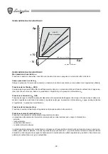
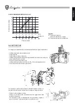
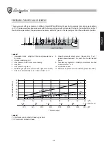
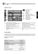
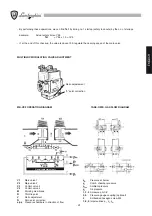
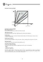
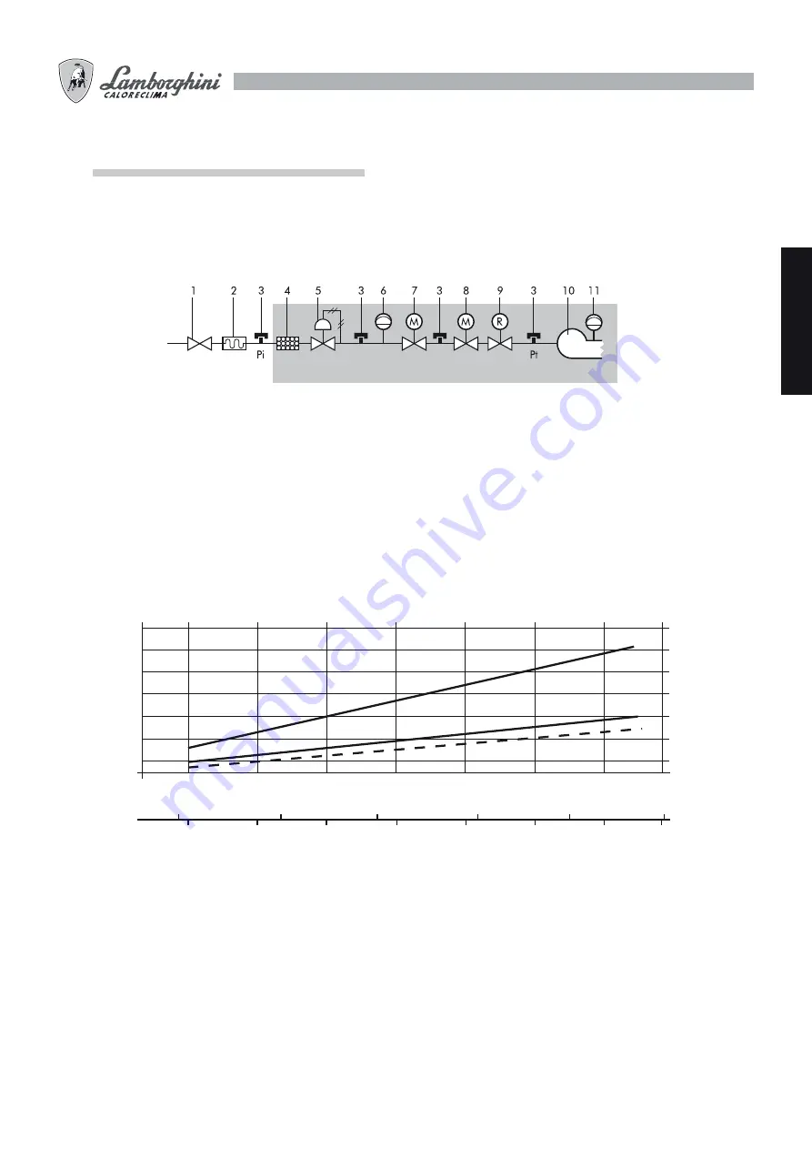
Legend
Pi Inlet pressure (combustion head + gas train)
Pt Pressure at combustion head
Thermal output
MULTIBLOC - 3/4” (Pi)
MULTIBLOC - 1 1/4” (Pi)
2
12
16
20
24
(Pt)
28
32
36
40
120
100
160
200
240
280
320
360
400
11
20
29
38
47
56
150
200
250
300
350
m
3
/h
kW
kcal/h x 10
Pressure loss (mbars)
PRESSURE CURVES/GAS DELIVERY
These curves show the gas pressure, in millibars, (at points
Pi
and
Pt
along the gas train) necessary to produce a given delivery
in m
3
/h. The pressures have been measured with the burner working and with a pressure of 0 mbar in the combustion chamber. If
the chamber is pressurized, the gas pressure necessary will be that given in the diagram plus that in the combustion chamber.
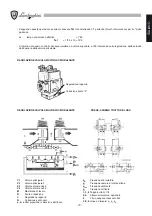
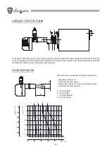
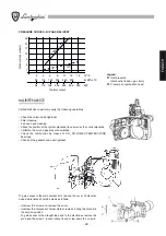
BASIC GAS TRAIN
Legend
1 Interception cock - airtight at 1 bar and pressure loss
0,5 mbar.
2 Vibration-damping
joint
3 Gas pressure point for pressure reading
4 Gas
filter
5 Gas pressure regulator
6 Minimum gas pressure control device (pressure switch)
7 Class A solenoid safety valve. Closure time Tc
1”.
8 Class A solenoid safety valve. Closure time Tc
1”.
Ignition power between 10% and 40% of rated thermal
power.
9 Gas delivery regulator, normally incorporated in either
solenoid valve 7 or 8.
10 Combustion head.
11 Minimum air pressure control device (pressure switch)
Summary of Contents for EM 40/2-E
Page 2: ......
Page 25: ...25 ITALIANO...
Page 47: ...47 ENGLISH...
Page 69: ...69 FRAN AIS...
Page 91: ...91 DEUTSCH...
Page 113: ...113 ESPA OL...
Page 115: ...115 a b c d CO2 CO2 CO2...
Page 116: ...116 119 133...
Page 120: ...120 2 n 4 3 4 5 1 A B C D...
Page 121: ...121 2...
Page 126: ...126 3 sec 3 sec LME 10...
Page 127: ...127 B 1 2 3 B H EM 35 E H H EM 40 2 E EM 40 M E H fi 1 max E E 1 E 2 E VE 2 2 14 10 13 SQN 71...
Page 132: ...132 3 A CO2 CO2 CO2 8 5 10 11 12 B P CO CO CO 0 1 160 C 220 C TPR TS B P...
Page 134: ...134 1 A B A B 2 A B C A B C 3 A A...
Page 135: ......

