- 32
-
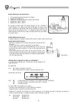
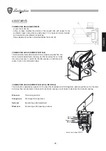
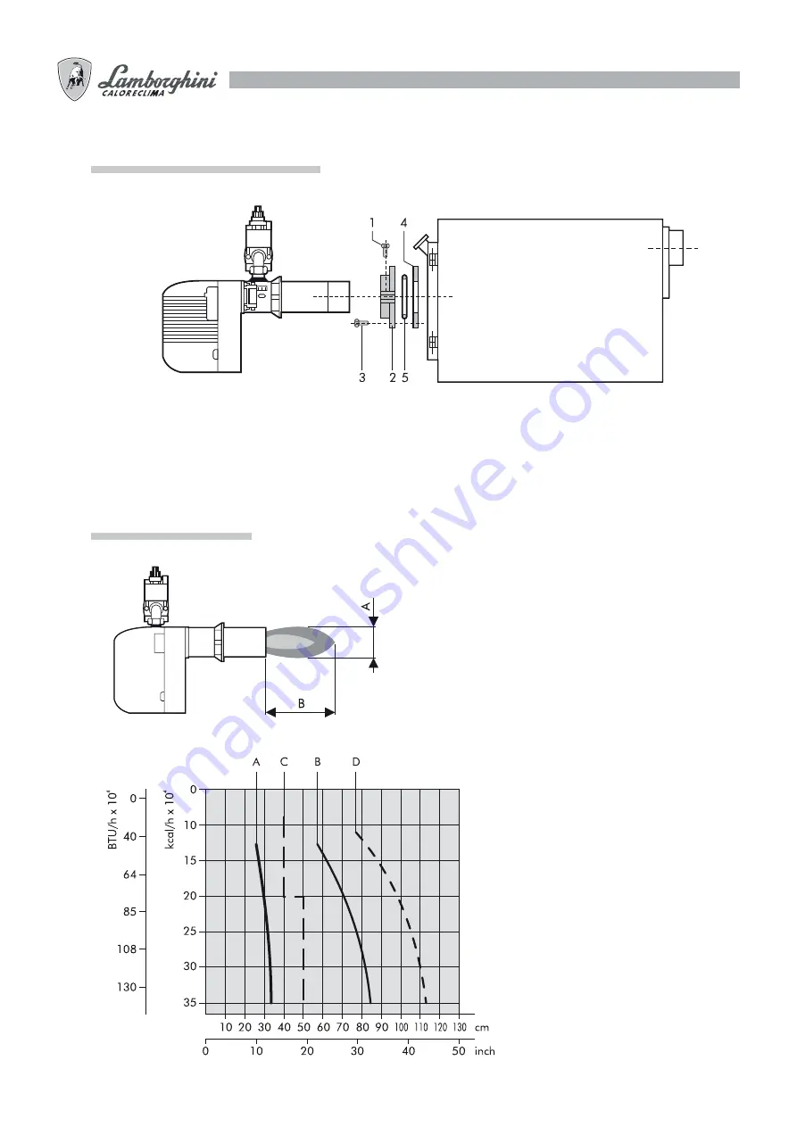
ASSEMBLY ONTO THE BOILER
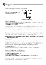
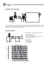
Fix flange
2
to the boiler using 4 screws
3
interposing the insulation gasket
4
and the possible insulating cord
5
. Insert the
burner in the flange so that the draught tube penetrates into the combustion chamber by the length suggested by the boiler
manufacturer. Tighten screw
1
to lock the burner in position.
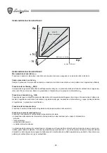
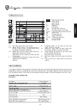
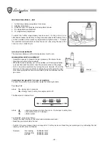
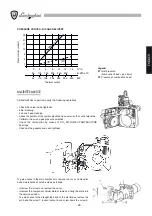
FLAME DIMENSIONS
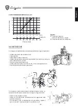
The dimensions are indicative only being influenced by:
- excessive quantity of air;
- combustion chamber shape;
- development of gas path in the boiler (direct/reverse);
- combustion chamber pressure.
A Flame
diameter
B Flame
length
C Test tube diameter
D Test tube length
Summary of Contents for EM 40/2-E
Page 2: ......
Page 25: ...25 ITALIANO...
Page 47: ...47 ENGLISH...
Page 69: ...69 FRAN AIS...
Page 91: ...91 DEUTSCH...
Page 113: ...113 ESPA OL...
Page 115: ...115 a b c d CO2 CO2 CO2...
Page 116: ...116 119 133...
Page 120: ...120 2 n 4 3 4 5 1 A B C D...
Page 121: ...121 2...
Page 126: ...126 3 sec 3 sec LME 10...
Page 127: ...127 B 1 2 3 B H EM 35 E H H EM 40 2 E EM 40 M E H fi 1 max E E 1 E 2 E VE 2 2 14 10 13 SQN 71...
Page 132: ...132 3 A CO2 CO2 CO2 8 5 10 11 12 B P CO CO CO 0 1 160 C 220 C TPR TS B P...
Page 134: ...134 1 A B A B 2 A B C A B C 3 A A...
Page 135: ......

