ERA F 23 - 32 - 45 - 56
8
EN
3. SERVICE AND MAINTENANCE
All adjustment, conversion, commissioning and maintenance operations described be-
low must only be carried out by Qualified Personnel (meeting the professional technical
requirements prescribed by the current regulations) such as those of the Local After-
Sales Technical Service.
LAMBORGHINI
declines any liability for damage and/or injury caused by unqualified and
unauthorised persons tampering with the unit.
3.1 Adjustments
Gas conversion
The unit can operate on Natural Gas or LPG and is factory-set for use with one of these
two gases, as clearly shown on the packing and on the dataplate. Whenever a different
gas to that for which the unit is arranged has to be used, a conversion kit will be required,
proceeding as follows:
1.
Replace the nozzles at the main burner, inserting the nozzles specified in the tech-
nical data table in sec. 4.3, according to the type of gas used
2.
Modify the parameter for the type of gas:
•
switch the boiler to standby mode
•
press the RESET button
R
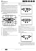
(detail 6 - fig. 1) for 10 seconds: the display shows
“
TS
“ flashing
•
press the RESET button
R
(detail 6 - fig. 1): the display shows “
P01
“.
•
Press the DHW buttons fig. 1 (details 1 and 2 - ) to set parameter 00 (for oper-
ation with natural gas) or 01 (for operation with LPG).
•
Press the RESET button
R
(detail 6 - fig. 1) for 10 seconds.
•
the boiler will return to standby mode
3.
Adjust the burner minimum and maximum pressures (ref. relevant section), setting
the values given in the technical data chart for the type of gas used
4.
Apply the sticker contained in the conversion kit, near the dataplate as proof of the
conversion.
TEST mode activation
Press the heating buttons (details 3 and 4 - fig. 1
) at the same time for 5 seconds to
activate
TEST mode. The boiler lights at the maximum heating power set as described
in the following section.
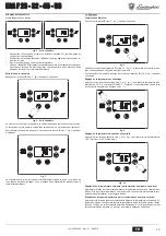
The heating symbol (detail 13 - fig. 1) and DHW symbol (detail 9 - fig. 1) flash on the dis-
play; the heating power will be displayed alongside.
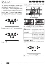
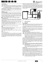
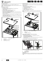
fig. 17 - TEST mode (heating power = 100%)
To deactivate TEST mode, repeat the activation sequence.
TEST mode is automatically disabled in any case after 15 minutes.
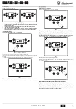
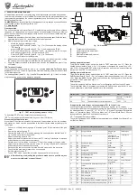
Pressure adjustment at burner
Since this unit has flame modulation, there are two fixed pressure values: the minimum
and maximum, which must be as specified in the technical data table according to the
type of gas.
•
Connect a suitable pressure gauge to pressure point “B” downstream of the gas
valve.
•
Remove the protection cap “D”.
•
Operate the boiler in TEST mode by pressing the heating buttons (details 3 and 4 -
fig. 1) at the same time for 5 seconds.
•
Adjust the heating power to 100.
•
Adjust the maximum pressure with the screw "G", turning it clockwise to increase
and anticlockwise to decrease the pressure.
•
Detach one of the two faston connectors "C" from the modureg on the gas valve.
•
Adjust the minimum pressure with the screw "E", turning it clockwise to decrease
and anticlockwise to increase the pressure.
•
Reconnect the faston connector removed from the modureg on the gas valve.
•
Check that the maximum pressure has not changed.
•
Refit the protection cap “D”.
•
To end TEST mode, repeat the activation sequence or wait 15 minutes.
A
After checking or adjusting the pressure, make sure to seal the adjust-
ment screw with paint or a specific seal.
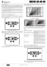
fig. 18 - Gas valve
B
Pressure point downstream
E
Minimum pressure adjustment
C
Modureg cable
G
Maximum pressure adjustment
D
Protection cap
Heating power adjustment
To adjust the heating power, switch the boiler to TEST mode (see sec. 3.1). Press the
heating buttons (details 3 and 4 - fig. 1) to increase or decrease the power (min. = 00 -
max. = 100). Press the RESET button within 5 seconds and the max. power will remain
that just set. Exit TEST mode (see sec. 3.1).
Lighting power adjustment
To adjust the lighting power, switch the boiler to TEST mode (see sec. 3.1). Press the
DHW buttons (details 1 and 2 - fig. 1) to increase or decrease the power (min. = 00 - max.
= 60). Press the RESET button within 5 seconds and the lighting power will remain that
just set. Exit TEST mode (see sec. 3.1).
Service menu
The card is equipped with two Menus: one for configuration and the other for Service.
The configuration Menu is accessed by pressing the DHW buttons together for 10 sec-
onds. 2 parameters, modifiable only from card, are available.
If replacing the card, always set the parameter P01 to 1=Cast iron.
To exit the configuration Menu, press the DHW buttons together for 10 seconds.
The card Service Menu is accessed by pressing the Reset button for 10 seconds. Press
the Heating buttons to select "tS", "In", "Hi" or "rE". tS” means Transparent Parameters
Menu, “In” Information Menu, “Hi” History Menu, and “rE” History Menu Reset. After se-
lecting the Menu, press the Reset button to access it.
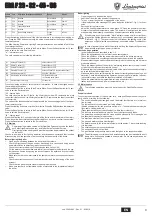
"tS” - Transparent Parameters Menu
The card is equipped with 24 transparent parameters also modifiable from Remote Con-
trol (Service Menu):
IIII
III
III
IIII
IIII
III
III
IIII
IIII
III
III
IIII
IIII
III
III
IIII
IIII
III
III
IIII
IIII
III
III
IIII
Remote control
Card
Description of transparent parameters
Range
Default
NO
P01
Exchanger type selection
0=Copper
1=Cast iron
1=Cast iron
NO
P02
Boiler shell Warm-up activation temperature
0-80°C
0°C
Remote
Control
Card
Description of transparent parameters
Range
Default
01
P01
Gas type selection
0=Natural gas
1=LPG
0=Natural gas
02
P02
Boiler type selection
1=Heating only
2=Storage with probe
3=Storage with ther-
most.
1=Heating only
03
P03
Absolute min. power
0-100%
0%
04
P04
Lighting power
0-60%
50%
05
P05
Not used
Not modifiable
0
06
P06
Heating train
1-20°C/min
5°C/min
07
P07
Heating pump Post-Circulation
0-20 minutes
6 minutes
08
P08
Heating standby time
0-10 minutes
2 minutes
09
P09
Max. heating power
0-100%
100%
10
P10
Pump operation
0=Post-Circulation
1=Continuous
0=Post-Circulation
11
P11
Pump deactivation temperature during Post-Cir-
culation
0-100°C
20°C
12
P12
Max. heating temperature
31-85°C
85°C
13
P13
DHW pump Post-Circulation
0-255 seconds
30 seconds
14
P14
DHW standby time
0-255 seconds
120 seconds
15
P15
DHW max. power
0-100%
100%
16
P16
DHW user max. setpoint
55-65°C
--
17
P17
Hot water tank activation hysteresis temperature 0-20°C
--
18
P18
Hot water tank preparation delivery temperature 70-85°C
--
+
Manometro
B
Ingresso
Gas
Uscita
Gas
A
F
C
G
E
D
cod. 3540L893 - Rev. 01 - 03/2018


