51
NO WATER
ALARM
NO WATER
ALARM
;;;
;;;
;;;
;;;
;;;
;;;
;;;
;;;
;;;
;;;
;;;
;;;
;;;
;;;
;;;
;;;
;;;
;;;
;;;
;;;
;;;
;;;
;;;
;;;
;;;
;;;
;;;
;;;
;;;
;;;
;;;
;;;
;;;
;;;
;;;
;;;
;;;
;;;
;;;
;;;
;;;
;;;
;;;
;;;
;;;
;;;
;;;
;;;
;;;
;;;
;;;
;;;
;;;
;;;
;;;
;;;
;;;
;;;
;;;
;;;
;;;
;;;
;;;
;;;
;;;
;;;
;;;;;;;;;;;;;;;;;
;;;;;;;;;;;;;;;;;
;;;;;;;;;;;;;;;;;
;;;;;;;;;;;;;;;;;
;;;;;;;;;;;;;;;;;
;;;;;;;;;;;;;;;;;
;;;;;;;;;;;;;;;;;
;;;;;;;;;;;;;;;;;
;;;;;;;;;;;;;;;;;
;;;;;;;;;;;;;;;;;
;;;;;;;;;;;;;;;;;
;;;;;;;;;;;;;;;;;
;;
;;
;;
;
;
;;
;;
;
;
;;
;;
;
;
;;;
;;;
;;;
;;
;;
;
;;;;;;;;;;;;;;;;;;
;;;;;;;;;;;;;;;;;;
;;;;;;;;;;;;;;;;;;
;;;;;;;;;;;;;;;;;;
;;;;;;;;;;;;;;;;;;
;;;;;;;;;;;;;;;;;;
;;;;;;;;;;;;;;;;;;
;;;;;;;;;;;;;;;;;;
;;;;;;;;;;;;;;;;;;
;;;;;;;;;;;;;;;;;;
;;;;;;;;;;;;;;;;;;
;;;;;;;;;;;;;;;;;;
;;;;;;;;;;;;;;;;;;
;;;;;;;;;;;;;;;;;;
;;;;;;;;;;;;;;;;;;
;;;;;;;;;;;;;;;;;;
;;;;;;;;;;;;;;;;;;
;;;;;;;;;;;;;;;;;;
;;;;;;;;;;;;;;;;;;
;;;;;;;;;;;;;;;;;;
;;
;;
;;
;;
;;
;;
;;
;;
;;
;;
;;
;;
;;
;;
;;
;;
;;
;;
;;
;;
;;
;;
;;
;;
;;
;;
;;
;;
;;
;;
;;
;;
;;
;;
;;
;;
;;
;;
;;
;;
;;
;;
;;
;;
;;
;;
;;
;;
;;
;;
;;
;;
;;
;;
;;
;;
;;
;;
;;
;;
;;
;;
;;
;;
;;
;;
;;;;;;;;;;;;;;;;;;
;;;;;;;;;;;;;;;;;;
;;;;;;;;;;;;;;;;;;
;;;;;;;;;;;;;;;;;;
;;;;;;;;;;;;;;;;;;
;;;;;;;;;;;;;;;;;;
;;;;;;;;;;;;;;;;;;
;;;;;;;;;;;;;;;;;;
;;;;;;;;;;;;;;;;;;
;;;;;;;;;;;;;;;;;;
;;;;;;;;;;;;;;;;;;
;;;;;;;;;;;;;;;;;;
;;;;;;;;;;;;;;;;;;
;;;;;;;;;;;;;;;;;;
;;;;;;;;;;;;;;;;;;
;;;;;;;;;;;;;;;;;;
;;;;;;;;;;;;;;;;;;
;;;;;;;;;;;;;;;;;;
;;;;;;;;;;;;;;;;;;
;;;;;;;;;;;;;;;;;;
;;;;;;;;;;;;;;;;;;
;;;;;;;;;;;;;;;;;;
;;;;;;;;;;;;;;;;;;
;;;;;;;;;;;;;;;;;;
;;;;;;;;;;;;;;;;;;
;;;;;;;;;;;;;;;;;;
;;
;;
;;
;;
;
;
;;
;;
;;
;;
;;
;;
;;
;;
;;
;
;
;;
;;;
;;;
;;;
;;
;;
;;
;;
;;
;;
;
;
;
;
;
;
1009DIS1091
;;;;;;;;;;;;;;;;;;;;;;;;;;;;;;;;;;;;;;;
;;;;;;;;;;;;;;;;;;;;;;;;;;;;;;;;;;;;;;;
;;;;;;;;;;;;;;;;;;;;;;;;;;;;;;;;;;;;;;;
;
;
NO WATER
ALARM
NO WATER
ALARM
NO WATER
ALARM
1
1
2
3
4
4
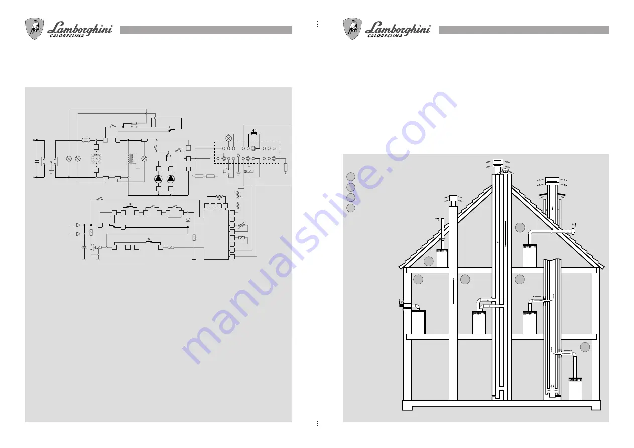
FLUE GAS DISCHARGE CONNECTION (MOD. MBS)
The boiler carries out combustion in a sealed chamber with respect to the room. For this reason no special
ventilation is required, and the boiler can be placed in storerooms, closets, technical compartments. Differ-
ent solutions are possible for the discharge of combustion products and the suction of air from the outside.
The boiler features two basic types of discharge/suction:
●
concentric-type discharge/suction
●
split-type discharge/suction.
The kits provided allow connection to concentric flues, ventilation flues, separate chimneys, etc. Several
possible solutions are shown in the figure.
For the positioning and distances of draught ends from windows, doors, etc., refer to the regulations in force.
DISCHARGE/SUCTION
1
concentric, from roof
2
concentric, from external wall
3
split, from separate flues
4
concentric, connections
to concentric flues
78
ESQUEMA ELÉCTRICO
LED 24MB W TOP-U/I
DESCRIPCIÓN
BM
Bobina modulante
BRC
Bobina relé circulador
BR3V
Bobina relé válvula 3 vías
BRS
Bobina relé de seguridad
C
Condensador
CA
Unidad de encendido
CF
Condensador antiinterferencias
electromagnéticas
CiB
Circulador acumulador
CiR
Circulador calefacción
CO
Contacto reloj
CRC
Contacto relé circulador
CR3V
Contacto relé válvula 3 vías
CRS
Contacto relé seguridad
D
Diodos
EC
Electrodo de control
No invierta el neutro con la fase.
La instalación tiene que ser conforme con la legislación local.
Realice una buena conexión de tierra.
EI
Interruptor Verano/Invierno
ES
Electrodo de descarga
FA
Filtro antiinterferencias
electromagnéticas
FC
Flue control
Fu
Fusible
F1
Fase
F2-F3
Neutro
IG
Interruptor general
OR
Reloj programador (opcional)
PR
Pulsador de rearme
P.Ri
Potenciómetro calefacción
PS
Presóstato de seguridad
R
Resistencia 1200 Ohm
RF
Resistencia antiinterferencias
electromagnéticas
SA
Luz indicadora de ALARM
SB
Luz indicadora de bloqueo
SF
Luz indicadora de funcionamiento
(color verde)
SMA
Indicador falta agua
SR
Sonda calefacción
SS
Sonda sanitario
T
Temporizador
TA
Termostato ambiente
TB
Termostato regulación
acumulador
TL
Termostato límite
TR
Transformador
TST
Termostato de seguridad
total (rearme)
VG
Válvula gas
c
na
nc
CRC
OR
L
N
IG
8
6
1
2
FC
FU
SA
F3
F2
F1
SF
22
14
21
20
CiR
CR3V
CRS
F"
12
13
TA
EI
23
TA
TA
4
5
CO
10
11
24
BRC
T
CRC
TR
25
16
17
TST
18
19
TL
BRS
BR3V
D
D
D
32
33
34
35
28
29
30
31
26
27
36
37
P.RI
SR
SS
R
+
-
BM
C
VG
PR
EC
CA
SB
1
3
4
7
9 11
15 17
2
5
6
8 10
12
14 16
18
19
13
PS
CiB
c
na
nc
TB
SMA
c
na
nc
RF
ES
20
FA
CF
1009DIS1082


