44
GB
0,00
2,00
4,00
6,00
8,00
10,00
12,00
14,00
mbar
0
200
400
600
800
1000 1200 1400 1600 1800 2000
kW
max
2
1
0,00
2,00
4,00
6,00
8,00
10,00
12,00
14,00
mbar
0
200
400
600
800
1000 1200 1400 1600 1800 2000
kW
1
min
2
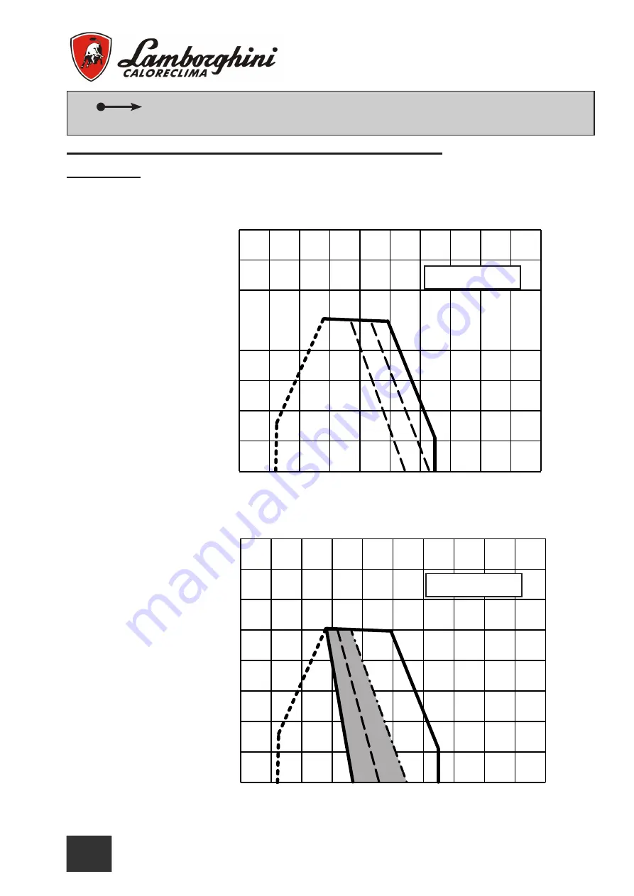
Adjust the air shutter in the position shown in the diagram, based on foreseen
flow control valve operation on the burner.
3)
It is necessary
to position the air ring (Fig. 5) in the desired working point referring to diagram A. Based on the
working point of the burner (supplied power / pressure in combustion chamber) a position is indicated (min - 1 - 2
- 3 - max) for the air adjustment ring which corresponds with the marks on rod T (Fig. 7).
Diagram B
Ex. If the burner should
operate at 1100kW with
a counter-pressure of 4
mbar, the air ring must
be positioned in corre-
spondence with mark 2
on rod T (Fig. 7)
In the event that the bur-
ner must operate in the
shaded sector of the
work range (therefore
with a gas reduction in-
serted), reference must
be made to diagram B
for the position of the air
adjustment ring. The in-
dicated values (min - 1)
refer to the marks on rod
T (Fig. 7).
In the event of opera-
tion in the shaded sec-
tor, for optimisation of
the air flow capacity,
the right damper must
be blocked (see “Blo-
cking right damper”
section).
Diagram A
Gas reduction combustion head regulation - (G 1300)


