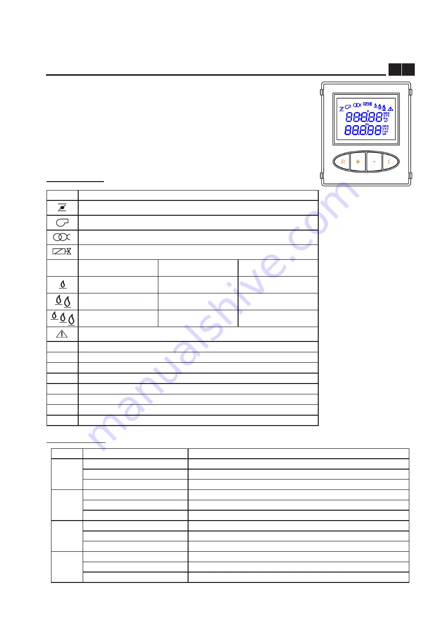
USER INTERFACE
M U
The control and command panel can be used to monitor
the status of the burner, access the diagnostic and confi-
guration menus of the system and release the appliance.
The control and command panel is composed of an LCD
with back-lit display area and 4 function keys.
Key functions
Icon meaning
ICON
MEANING
Air damper servo-motor
Fan motor
Ignition transformer
First stage solenoid valve
twO-staGe BUrNer
tHree-staGe BUrNer
MODUlatiNG BUrNer
First stage flame signal
First stage flame signal
Flame signal presence
Second stage flame signal
Second stage flame signal
Not used
Not used
Third stage flame signal
Not used
Anomaly signal
K
Not used
HRS
Hours
CYC
Cycles
Kg
Kilograms
m
3
Not used
Lux
Lux
uA
Not used
Hz
Hertz
KEY
DISPLAY
MEANING
R
NOrMal
Release appliance if in block conditions
MeNU
Go back to previous level menu
MODiFY ParaMeter
Exit the display mode without memorising
+
NOrMal
Not used
MeNU
Successive parameter or data
MODiFY ParaMeter
Increase parameter value
-
NOrMal
Not used
MeNU
Previous parameter or data
MODiFY ParaMeter
Decrease parameter value
i
NOrMal
Menu display mode
MeNU
Display next level menu
MODiFY ParaMeter
Confirm parameter modification


