background image

PNZ 30 - 50 - 75 - 100 - 130

MONTAGGIO - USO - MANUTENZIONE

ASSEMBLY - USE - MAINTENANCE

MONTAJE - USO - MANTENIMIENTO

BRUCIATORI DI NAFTE DESOLFORATE

SWEET NAPHTHA BURNERS

QUEMADORES DE FUEL PESADO DESULFURADO

Summary of Contents for PNZ 100

Page 1: ...PNZ 30 50 75 100 130 MONTAGGIO USO MANUTENZIONE ASSEMBLY USE MAINTENANCE MONTAJE USO MANTENIMIENTO BRUCIATORI DI NAFTE DESOLFORATE SWEET NAPHTHA BURNERS QUEMADORES DE FUEL PESADO DESULFURADO...

Page 2: ......

Page 3: ...carefully as they give important safety instructions regarding installation use and maintenan ce Keep this manual for future reference Installation must be carried out by qualified personnel who will...

Page 4: ...ZIA VALVOLE ELETTROMAGNETICHE 18 FUNZIONAMENTO REGOLARE DEL BRUCIATORE 19 PER SPEGNERE IL BRUCIATORE 19 IRREGOLARITA DI FUNZIONAMENTO 20 LAMBORGHINI CALOR S p A Dott Felice Bo Direttore Generale _____...

Page 5: ...montaggio del bruciatore o I apertura di accessi di ispezione disinserire la corrente elettrica e chiudere i rubinetti di adduzione del combustibile Non depositare contenitori con sostanze infiammabil...

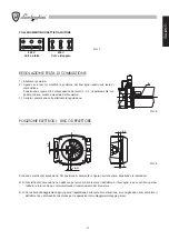
Page 6: ...i utilizzati deve consentire l apertura del bruciatore ed eventualmente della porta della caldaia I collegamenti elettrici devono essere effettuati esclusivamente da personale qualificato e devono ess...

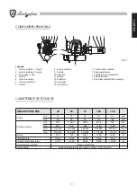
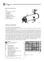
Page 7: ...rmatore 19 pomello regolazione boccaglio FIG 2 CARATTERISTICHE TECNICHE DESCRIZIONE PNZ 30 50 75 100 130 Portata min 18 19 29 37 65 kg h max 32 56 86 110 140 kg h Potenza termica min 202 216 5 330 4 4...

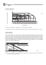
Page 8: ...PNZ funzionano con nafte desolforate la cui viscosit non superi i 12 15 E a 50 C La nafta perch possa essere polverizzata e quindi possa bruciare bene deve essere oppor tunamente preriscaldata a ques...

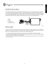
Page 9: ...te SCELTA GICLEUR I bruciatori mod PNZ sono a due fasi di partenza o due fiamme e pertanto corredati da due gicleur Si raccomanda l uso di gicleur a 60 a cono pieno semipieno La portata totale dei due...

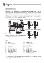
Page 10: ...L3 9 N TMAX RR 400 V 230 V CR CR MR MR N N BRR BRR 13 N MR F L1 L2 L3 9 N TMAX RR F IGR L1 L2 L3 9 N TMAX RR 400 V 230 V CR CR MR MR N N BRR BRR 13 N MR 13 N MR COLLEGAMENTI BRUCIATORI PNZ 30 50 75 1...

Page 11: ...a regolazione POSIZIONE ELETTRODI DISCO DEFLETTORE Si hanno 2 elettrodi di accensione Per posizionarli osservare la figura riportata sopra rispettando le indicazioni N B Gli elettrodi di accensione no...

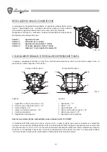
Page 12: ...EC tipo E Pompa SUNTEC tipo D Legenda 1 Aspirazione o attacco vacuometro 1 2 2 Ritorno e grano di by pass interno 1 2 3 Uscita all ugello 1 4 4 Attacco manometro pressione 1 8 5 Cavit preriscaldatore...

Page 13: ...aratura del termostato di minima del serbatoio preriscaldatore il bruciatore automaticamente partir controllare che la pressione in pompa a 22 26 Atm e che il vuoto non superi i 6 mH2 O Togliere il ma...

Page 14: ...vocomando dell aria comanda l apertura della valvola elettromagnetica di 2 fiamma ed ha cos termine il programma di avviamento del brucia tore Se per una qualsiasi causa non si ha formazione di fiamma...

Page 15: ...ustibile Accensione difettosa 3 lampeggi Libero 4 lampeggi Luci estranee alla partenza del bruciatore 5 lampeggi Libero 6 lampeggi Libero 7 lampeggi Troppe perdite di fiamma durante il funzionamento l...

Page 16: ...a scarica esistente fra le punte degli elettrodi Fase di funzionamento seconda fiamma il servocomando della serranda aria comanda l apertura della valvola elettromagnetica di seconda fiamma VE2 la naf...

Page 17: ...re l uno e l altro molto bene ed a lungo con benzina e gasolio Assicurarsi senza adoperare n spilli n altro che la benzina od il gasolio passino liberamente dal foro del gicleur battendo legermente co...

Page 18: ...lvola elettromagnetica 2 Bobina 3 Vite fissaggio cannotto 4 Cannotto 5 Pistone 6 Base fissaggio valvola elettromagnetica VALVOLA APERTURA GICLEUR Legenda 1 Supporto pistone 2 Molla pistone 3 Pistone 4...

Page 19: ...atore e per risparmiare combustibile sconsigliamo di variare ad ogni momento la temperatura di esercizio del bruciatore Una volta quindi fissata la temperatura di esercizio opportuno che il bruciatore...

Page 20: ...o male a Estrarre la fotoresistenza dalla sua sede e pulire con un panno la parte sensibile b Pulire i gicleurs o sostituirli Fiamma irregolare fiamma fumosa a Gicleurs che polverizzano male b Errata...

Page 21: ...21 ITALIANO...

Page 22: ...SYSTEM FUNCTIONING 34 MAINTENANCE 34 CLEANING THE ELECTRO MAGNETIC VALVES 36 REGULAR BURNER OPERATION 36 SWITCHING OFF THE BURNER 37 BURNER MALFUNCTIONING 37 LAMBORGHINI CALOR S p A Dott Felice Bo Gen...

Page 23: ...norms in force In case of doubt regarding air circulation it is first advisable to measure the concentration of carbon dioxide while the burning is working in maximum capacity and with its installatio...

Page 24: ...ged during transport In case of doubt do not use the burner and contact your supplier The packaging material wooden crate cardboard plastic bags polystyrene staples etc is a form of pollution and offe...

Page 25: ...nozzle regulation knob FIG 2 TECHNICAL CHARACTERISTICS DESCRIPTION PNZ 30 50 75 100 130 Capacity min 18 19 29 37 65 kg h max 32 56 86 110 140 kg h Thermal power min 202 216 5 330 4 421 6 740 kW max 3...

Page 26: ...hs according to the operation range PNZ burners run on de sulphured naphtha types whose viscosity does not exceed 12 15 E at 50 C Naphtha must be suitably preheated so it can be pulverised and therefo...

Page 27: ...rners have two ignition phases or two flames and are therefore equipped with two nozzles It is advisable to use nozzles at 60 C with full or half full cone The total capacity of the two nozzles must c...

Page 28: ...N TMAX RR 400 V 230 V CR CR MR MR N N BRR BRR 13 N MR F L1 L2 L3 9 N TMAX RR F IGR L1 L2 L3 9 N TMAX RR 400 V 230 V CR CR MR MR N N BRR BRR 13 N MR 13 N MR PNZ 30 50 75 100 130 BURNER CONNECTIONS PNZ...

Page 29: ...obs once regulation is completed ELECTRODE DEFLECTION DISK POSITION There are 2 ignition electrodes Position them according to the figure above N B The ignition electrodes must never touch the deflect...

Page 30: ...4 1 4 2 SUNTEC pump type E SUNTEC pump type D CAPTION 1 Vacuum meter suction or attachment 2 Return and internal by pass grub screw 3 Outlet to nozzle 4 Pressure manometer attachment 1 8 5 Pre heater...

Page 31: ...e heater tank is reached the burner will start automatically make sure the pressure in the pump is within 22 and 26 atm and that vacuum does not exceed 6 mH2 O Remove the manometer and the vacuum mete...

Page 32: ...he 2nd flame electro magnetic valve by means of the air servo command consent The burner ignition program will therefore finish If for any reason no flame is formed the equipment will stop in its safe...

Page 33: ...or Scarce burner regulation no fuel Faulty ignition 3 blinks Free 4 blinks Unexpected lights at burner ignition 5 blinks Free 6 blinks Free 7 blinks Too much flame loss during operation repetition lim...

Page 34: ...being ignited by the discharge between the extremities of the electrodes Second flame operation phase the servo command of the air gate will order the opening of the second flame electro magnetic valv...

Page 35: ...Use an Allen wrench to unscrew the nozzle dispenser fig 18 Rinse both very well and for a long time using gasoline and diesel Without using needles or anything similar make sure that the gasoline or t...

Page 36: ...pressure at the nozzle will drop although the manometer on the pump will detect normal pressure REGULAR BURNER OPERATION The burner has automatic operation when supplied by means of the main switch it...

Page 37: ...ectrode tips b Fuel does not reach the burner c Clogged nozzles or electro magnetic valves d No discharge on the electrodes a Clean electrode tips and set them at their correct distances b Check fuel...

Page 38: ...50 LIMPIEZA DE LAS V LVULAS ELECTROMAGN TICAS 52 FUNCIONAMIENTO CORRECTO DEL QUEMADOR 53 PARA APAGAR EL QUEMADOR 53 IRREGULARIDADES EN EL FUNCIONAMIENTO 54 LAMBORGHINI CALOR S p A Dott Felice Bo Direc...

Page 39: ...uiere la red el ctrica y la de alimentaci n del combustible b que el quemador sea compatible con la potencia de la caldera c que la aportaci n de aire comburente y la expulsi n de los humos tenga luga...

Page 40: ...rbida que est indicado en la placa de datos del quemador y en este manual Si el cable de alimentaci n del quemador tiene alg n defecto ha de sustituirlo solamente el personal t cnico cualificado No ha...

Page 41: ...10 235 H m n m x 172 225 160 200 283 283 318 1 3 2 4 5 6 18 17 7 8 9 16 15 14 19 10 11 12 13 Descripci n 1 V lvula el ctrica 1a etapa 2 V lvula el ctrica 2a etapa 3 Base acoplamiento VE1 4 Ventilador...

Page 42: ...84 200 362 600 637 000 kcal h m x 313 600 548 800 842 800 1 078 000 1 372 000 kcal h Motor 370 740 1500 1500 1800 W Transformador 10 30 10 30 10 30 10 30 10 30 kV mA Potencia total absorbida 3 200 5 6...

Page 43: ...atenerse tajantemente a las instruc ciones si las hay de la casa fabricante es muy importante respetar la longitud de embocadura requerida sta se puede ajustar f cilmente desplazando el quemador en la...

Page 44: ...MAX RR 400 V 230 V CR CR MR MR N N BRR BRR 13 N MR F L1 L2 L3 9 N TMAX RR F IGR L1 L2 L3 9 N TMAX RR 400 V 230 V CR CR MR MR N N BRR BRR 13 N MR 13 N MR CONEXIONES QUEMADORES PNZ 30 50 75 100 130 CONE...

Page 45: ...ar las tuercas una vez efectuada la regulaci n POSICI N DE LOS ELECTRODOS DISCO DEFLECTOR Hay dos electrodos de encendido Para colocarlos observen la figura de arriba y respeten las indicaciones Nota...

Page 46: ...6 bar B 5 3 6 1 1 6 5 2 3 4 4 1 4 2 Bomba SUNTEC tipo E Bomba SUNTEC tipo D DESCRIPCI N 1 Aspiraci n o toma vacu metro 1 2 2 Toma retorno 1 2 y regulaci n by pass interior 3 Salida al pulverizador 1 4...

Page 47: ...ivel de tarado del termostato de m nima del dep sito precalentador el quemador arrancar autom ticamente Controlar que la presi n en la bomba sea de 22 26 atm y que el vac o no supere 6 mH2O Quitar el...

Page 48: ...control gracias al asenso del servomando del aire acciona la apertura de la v lvula electromagn tica de la segunda llama y termina as el programa de arranque del quemador Si por cualquier causa no se...

Page 49: ...Encendido defectuoso 3 parpadeos Libre 4 parpadeos Luces extra as cuando arranca el quemador 5 parpadeos Libre 6 parpadeos Libre 7 parpadeos Demasiadas p rdidas de llama durante el funcionamiento lim...

Page 50: ...las puntas de los electrodos Fase de funcionamiento de la segunda llama El servomando de la clapeta del aire acciona la apertura de la v lvula electromagn tica de segunda llama VE2 y el fuel pesado se...

Page 51: ...or del pulverizador v ase la fig 18 Enjuagar los dos muy bien con gasolina o gas leo Asegurarse sin usar agujas ni otras cosas que la gasolina o el gas leo pasen libremente por el orificio del pulveri...

Page 52: ...blaje v lvula electromagn tica 2 Bobina 3 Tornillo fijaci n tubo 4 Tubo 5 Pist n 6 Base fijaci n v lvula electromagn tica V LVULA APERTURA PULVERIZADOR DESCRIPCI N 1 Soporte pist n 2 Muelle pist n 3 P...

Page 53: ...jamos variar a cada momento la temperatura de funcionamiento de quemador Una vez que se establezca la temperatura de funcionamiento es conveniente que el quemador que es autom tico se regule solo Si e...

Page 54: ...a Sacar la fotorresistencia de su alojamiento y limpiarla con un pa o la parte sensible b Limpiar los pulverizadores o cam biarlos Llama irregular llama humosa a Los pulverizadores pulverizan mal b E...

Page 55: ......

Page 56: ...riserva il diritto di apportare senza obbligo di preavviso tutte le modifiche che ritiene pi opportuno per l evoluzione del prodotto The illustrations and data are indicative and non binding LAMBORGH...

Reviews: