- 32
-
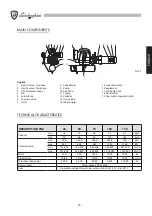
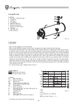
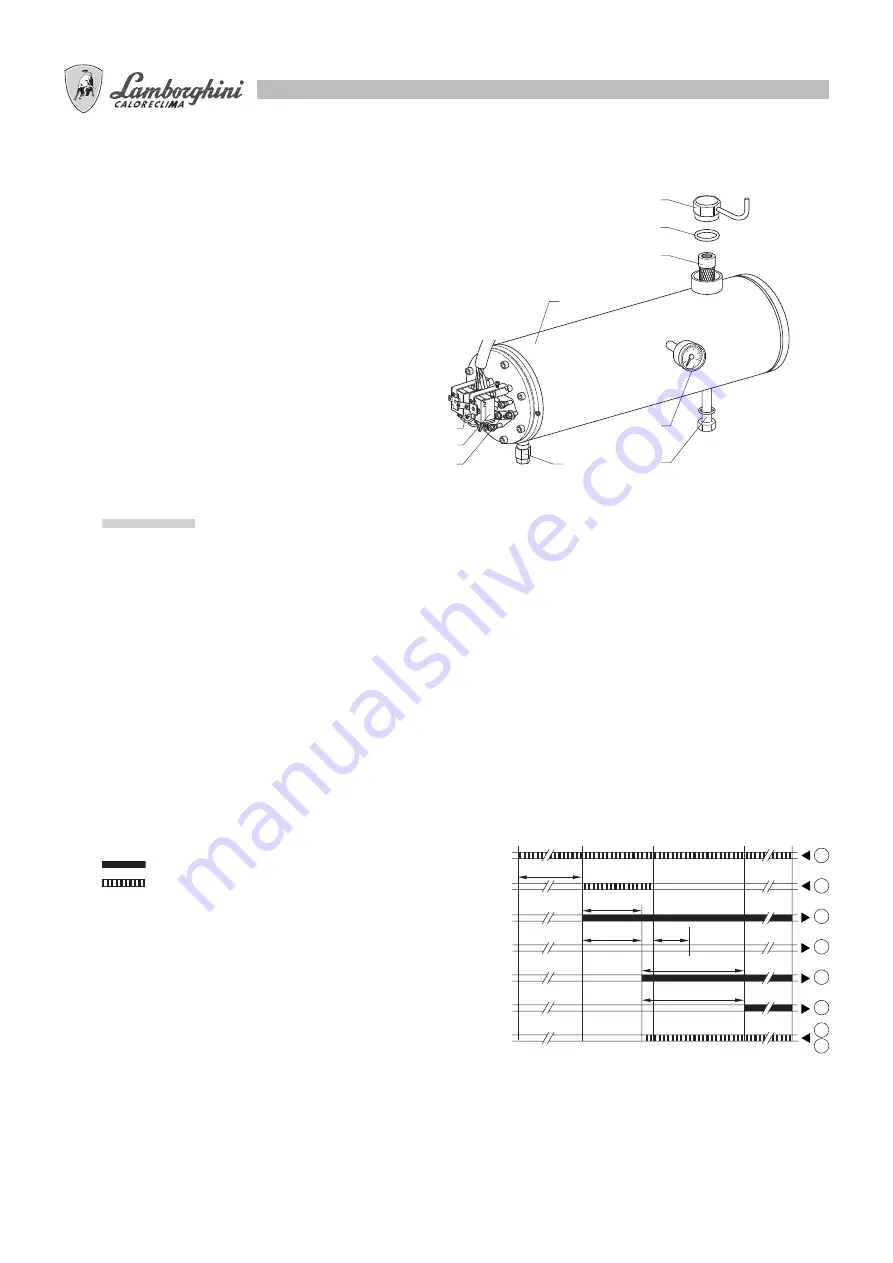
PRE-HEATER TANK
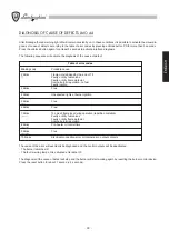
CAPTION
1 Tank pipe – attachment base
2 Sealing
ring
3 Tank
filter
4 Thermometer
5 Minimum
thermostat
6 Maximum
thermostat
7 Electric resistance clamps
8 Drain
tap
9 Pre-heater
tank
10 Filter fixing rod
CHECKLIST
- Make sure the equipment is working properly.
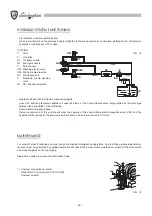
- Make sure the IGNITION program of the burner is the regular one; stages should follow this sequence:
When command thermostat TC and minimum thermostat are closed the device is supplied and checks the various inter-
nal electric circuits; the burner motor and the ignition transformer start working. Pre-ventilation and pre-ignition phases
begin (t1 and t3); electro-magnetic valve VE1 is excited and the fuel reaches the first-flame nozzle. The pre-ventilation
phase is over and the safety period begins (t2), during which flame should form regularly. Discharge between the extre-
mities of electrodes continues, giving place to post-ignition (t3n); within 5 seconds after VE1 excitation the equipment
will order the opening of the 2nd-flame electro-magnetic valve by means of the air servo command consent. The burner
ignition program will therefore finish. If, for any reason, no flame is formed, the equipment will stop in its safety position,
signalled by red light LR on the switchboard (see fig. 6) which will remain on. Once the equipment is blocked the burner
motor will stop, as will the ignition transformer; at this point the washing electro-magnetic valve is unexcited and releases
the flow of fuel in the boiler.
- To unblock the burner press unblock button PS (fig. 6).
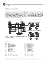
LOA 44.../LMO 44
CAPTION
TC Boiler
thermostat
T min
Minimum thermostat
MB Burner
motor
VE1
1st flame electro-magnetic valve
VE2
2nd flame electro-magnetic valve
FR Photoresistance
TR Ignition
transformer
tw
Fuel pre-heating time - according to the system use
t1
Pre-ventilation
time
~
25
s
t3
Pre-ignition
time
~
25
s
t2
Safety
time
max.
5
s
t3n
Post-ignition time
(~ 2 s* LOA 44) (~ 5 s* LMO 44)
t4
Time between “VE1 and VE2” command
~ 5 s*
Block due to lack of flame – > 1 s
* According to the moment when the flame appears
1
2
3
6
5
7
8
9
10
4
Tmin.
MB
TR
VE1
VE2
FR
t1
t3
t w
t 2
t3n
t 4
TC
1
1
3
6
4
5
11
12
signals leaving the device
incoming necessary signals
FIG. 12
FIG. 13


