Taura 24 MCS W TOP
28
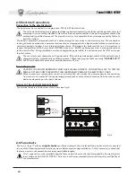
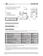
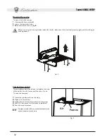
• Check that the maximum pressure has not changed.
• Reconnect the pressure compensation tube
“H”
.
• Put the protective cap
“D”
back on.
• To end TEST mode, select another mode.
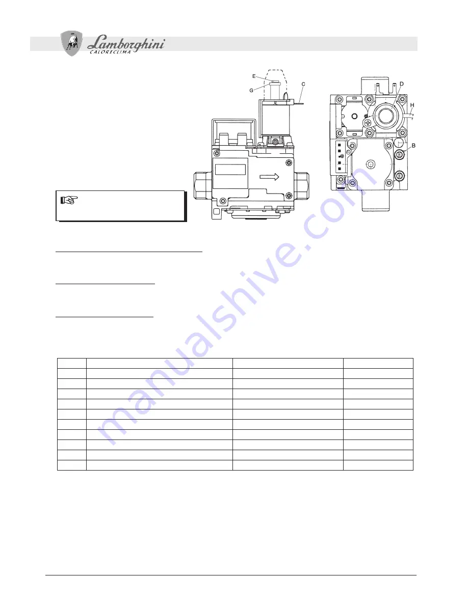
Key
B
Pressure
point
C
Modureg
cable
D
Protective
cap
E
Minimum pressure adjustment
G
Maximum pressure adjustment
Fig. 3
After checking or adjusting the pressure,
it is mandatory to seal the adjustment
screw with paint or a specific seal.
Adjusting the maximum heating output
Refer to the Installer parameters menu section
Ignition power adjustment
Refer to the Installer parameters menu section
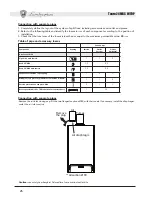
Installer Parameters menu
The card is equipped with 10 transparent parameters: modifiable from Remote Control (Service parameters menu)
and from the same (Installer Parameters Menu except the last two, 9 and 10):
Num.
Parameters menu
Range
Default
1
Max. heating power
0-100%
100%
2
Gas type selection
0=Natural gas,1=LPG
0=Natural gas
3
Lighting Power
0-60%
50%
4
Heating idle time
0=0minutes, 1=2.5 minutes
1=2.5 minutes
5
Heating pump Post-Circulation
0=0minutes, 1=2.5 minutes
1=2.5 minutes
6
Heating user max. setpoint
30°C, 40°C, 85°C
85°C
7
Hot water user max. setpoint
0=55°C, 1=65°C
0=55°C
8
Boiler shutdown in hot water mode
0=Fixed,1=Tied to setpoint
1=setp.
9
Heating ramp
1-20°C/min
10°C/min
10
Mains Voltage Frequency
0=50Hz,1=60Hz
0=50Hz
Remote Timer Control modification occurs by entering its Service parameters menu (refer to the relevant manual):
the order and range correspond exactly to that given in the table.
Modification from card occurs as follows.
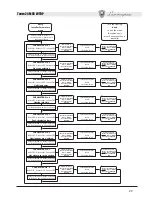
The parameters, named in the previous table P1÷P8, can be displayed and possibly modified from the Installer Pa-
rameters menu by decoding of the LEDs and position, for different time intervals, of the selector. The method for
accessing, displaying and/or modifying a number of parameters and exiting the menu is described by means of the
following flow chart.


