background image

EL-DB EVO N

3

EN

cod. 3541P770  -  Rev. 00  -  06/2018

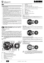
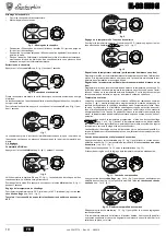
Boiler lighting

Open the fuel on-off valves.

Switch on the power to the unit.

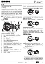
fig. 5 - Boiler lighting

For the following 120 seconds the display will show FH which identifies the heating
system air venting cycle.

During the first 5 seconds the display will also show the card software version.

When the message FH disappears, the boiler is ready to operate automatically
whenever domestic hot water is drawn or in case of a room thermostat demand.

Turning the boiler off

Press the 

on/off

 button (detail 9 - fig. 1) for 1 second.

fig. 6 - Turning the boiler off

When the boiler is turned off, the PCB is still powered.
Domestic hot water and heating are disabled. The antifreeze system remains activated.
To relight the boiler, press the 

on/off

 button (detail 9 fig. 1) again for 1 second.

fig. 7

The boiler will be immediately ready to operate whenever domestic hot water is drawn
or in case of a room thermostat demand.

2.4 Adjustments
Summer/Winter Switchover

Press the 

summer/winter

 button (detail 6 - fig. 1) for 1 second.

fig. 8

The display activates the Summer symbol (detail 27 - fig. 1): the boiler will only deliver
domestic hot water. The antifreeze system remains activated.
To deactivate the Summer mode, press the 

summer/winter

 button (part. 6 - fig. 1) again

for 1 second.

Heating temperature setting

Use the 

heating buttons

 (details 3 and 4 - fig. 1) to adjust the temperature from a min.

of 30°C to a max. of 80°C.

In any case it is advisable not to operate the boiler below 45°C

.

fig. 9

DHW temperature adjustment

Use the DHW buttons 

 (details 1 and 2 - fig. 1) to adjust the temperature

from a min. of 10°C to a max. of 65°C.

fig. 10

Room temperature adjustment (with optional room thermostat)

Using the room thermostat, set the temperature desired in the rooms. If the room ther-
mostat is not installed the boiler will keep the heating system at its setpoint temperature.

Room temperature adjustment (with optional remote timer control)

Using the remote timer control, set the temperature desired in the rooms. The boiler unit
will set the system water according to the required room temperature. For information on
the remote timer control, please refer to its user's manual.

Sliding temperature

When the optional external probe is installed the control panel display (detail 5 - fig. 1)
shows the actual outside temperature read by the probe. The boiler control system op-
erates with "Sliding Temperature". In this mode,  the temperature of the heating system
is adjusted according the outside weather conditions, in order to ensure high comfort and
energy saving throughout the year. In particular, as the outside temperature increases,
the system delivery temperature is decreased according to a specific "compensation
curve".
With Sliding Temperature adjustment, the temperature set with the heating buttons

 (details 3 and 4 - fig. 1) becomes the maximum system delivery tempera-

ture. It is advisable to set a maximum value to allow system adjustment throughout its
useful operating range.
The boiler must be adjusted at the time of installation by qualified personnel. Possible
adjustments can in any case be made by the user to improve comfort.

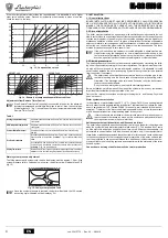
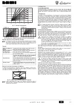
Compensation curve and curve offset

Press the 

mode

 button (detail 10 - fig. 1) once to display the actual compensation curve

(fig. 11), which can be modified with the 

DHW buttons

 (details 1 and 2 - fig. 1).

Adjust the required curve from 1 to 10 according to the characteristic (fig. 13).
By setting the curve to 0, sliding temperature adjustment is disabled.

fig. 11 - Compensation curve

Press the 

heating buttons

 (details 3 and 4 - fig. 1) to access parallel curve offset

(fig. 14), modifiable with the 

DHW buttons

 (details 1 and 2 - fig. 1).

fig. 12 - Curve parallel offset

Press the 

mode

 button (detail 10 - fig. 1) again to exit parallel curve adjustment mode.

eco

comfort

m

od

e

r e s e t

eco

comfort

m

o

de

r e s e t

eco

comfort

m

o

de

r e s et

eco

bar

eco

comfort

m

o

de

r e s e t

eco

bar

eco

comfort

m

o

de

r e s e t

eco

bar

eco

comfort

m

od

e

r e s e t

eco

bar

Summary of Contents for EL-DB EVO N 32

Page 1: ...EL DB N 32 47 62 78 95 cod 3541P770 Rev 00 06 2018 INSTRUCTIONS FOR USE INSTALLATION AND MAINTENANCE INSTRUCTIONS D UTILISATION D INSTALLATION ET D ENTRETIEN RU 5 1 3541P770...

Page 2: ...production are only active with the optional hot water tank connect ed as indicated in sec 3 3 2 2 Control panel Panel fig 1 Control panel Panel legend 1 DHW temperature setting decrease button 2 DHW...

Page 3: ...perature adjustment with optional remote timer control Using the remote timer control set the temperature desired in the rooms The boiler unit will set the system water according to the required room...

Page 4: ...circuit Otherwise if the discharge valve cuts in and floods the room the boiler manu facturer cannot be held liable Do not use the water system pipes to earth electrical appliances Before installation...

Page 5: ...e earth wire must be left 2 cm longer than the others B The user must never change the unit s power cable If the cable gets damaged switch off the unit and have it changed solely by professionally qua...

Page 6: ...er supply to the boiler 2 Remove the front top and bottom panel 3 Open the door by undoing the knobs 4 Clean the inside of the boiler and the entire path of exhaust fumes using a tube brush or compres...

Page 7: ...EL DB EVO N 62 EL DB EVO N 62 EL DB EVO N 95 Number of elements no 3 4 5 6 7 Max heating capacity kW 28 3 41 9 56 6 71 3 84 6 Q Min heating capacity kW 22 4 22 3 33 4 44 5 55 8 Q Max heat output in h...

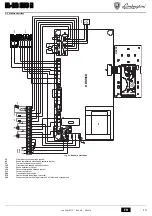
Page 8: ...tat optional 130 DHW circulating pump optional 138 External probe optional 139 Remote timer control optional 211 Burner connector 246 Pressure transducer 278 Double sensor heating safety 304 Stage 2 b...

Page 9: ...chaude sanitaire sont actives uniquement avec le ballon sanitaire optionnel comme indiqu au sez 3 3 2 2 Tableau des commandes Panneau fig 1 Panneau de contr le L gende panneau 1 Touche pour diminuer...

Page 10: ...istance la temp rature souhait e l in t rieur des pi ces La chaudi re r glera la temp rature dans le circuit d eau de l instal lation en fonction de la temp rature ambiante demand e Pour le fonctionne...

Page 11: ...appareils lectriques Avant l installation laver soigneusement toutes les tuyauteries de l installation afin d li miner toutes les impuret s ou r sidus risquant de compromettre le bon fonctionnement de...

Page 12: ...B Le c ble d alimentation de l appareil ne doit pas tre remplac par l utilisateur En cas d endommagement du c ble teindre l appareil et confier exclusive ment son remplacement un professionnel qualif...

Page 13: ...sont proscrire Nettoyage de la chaudi re 1 Couper l alimentation lectrique de la chaudi re 2 ter le panneau avant sup rieur et le panneau inf rieur 3 D visser les pommeaux de la porte pour l ouvrir 4...

Page 14: ...EVO N 47 EL DB EVO N 62 EL DB EVO N 72 EL DB EVO N 95 Nombre d l ments nbre 3 4 5 6 7 Puissance thermique maxi kW 28 3 41 9 56 6 71 3 84 6 Q Puissance thermique mini kW 22 4 22 3 33 4 44 5 55 8 Q Puis...

Page 15: ...mbiance option 130 Circulateur eau chaude sanitaire option 138 Sonde ext rieure option 139 Chronocommande distance option 211 Connecteur br leur 246 Transducteur de pression 278 Capteur double chauffa...

Page 16: ...al Number 1820G80021 18 20 G8 0021 B A B 0DQXIDFWXUHU 0DQXIDFWXUHU DGGUHVV Model RGH Qnw Hi PMS PMW Qn Hi tmax C D Pn 80 60 H2O Pn 50 30 12 Serial number DUFRGH 1 1 3URGXFWLRQ GDWH See the manual 5 IP...

Page 17: ...26 1 2 Comfort 12 13 1 Comfort 15 1 11 1 3 conomy COMFORT 15 1 ECO 15 1 ECO eco comfort 7 1 COMFORT eco comfort 7 1 1 3 4 B sez 2 3 5 120 FH 5 FH eco comfort m o d e r e s e t ecomfort bar 5 7 9 10 2...

Page 18: ...1 2 1 10 5 1 3 4 1 10 1 11 1 2 1 1 10 13 0 11 3 4 1 14 1 2 1 12 10 1 13 eco comfort m o d e r e s e t eco comfort m o d e r e s e t eco bar eco comfort m o d e r e s e t eco bar eco comfort m o d e r...

Page 19: ...5 A 120 FH 2 2 1 2 2 A 2 3 B cap 4 25 Fr 1 F 10 CaCO3 15 F 236 88 B 6 C 16 cap 4 4 LAMBORGHINI 16 8 9 10 11 ECO COMFORT Eco nomy 7 1 Comfort 7 1 20 30 40 50 60 70 80 90 85 20 30 40 50 60 70 80 90 85 1...

Page 20: ...3541P770 Rev 00 06 2018 2 4 A 2 5 B Y 3 3A 2 B HAR H05 VV F 3x0 75 2 8 B 230 A 17 2 6 3 LAMBORGHINI 3 1 TEST 3 4 1 5 TEST 24 1 12 1 18 TEST TEST TEST 15 3 2 B sez 1 3 sez 4 3 3 3 A A eco comfort m o...

Page 21: ...EL DB EVO N 21 RU cod 3541P770 Rev 00 06 2018 2 1 A 1 2 3 4 5 3 4 22 1 A 8 1 1 F 2 A01 A02 A03 A04 F07 X5 F09 F10 1 F11 F12 F13 X12 F14 2 F16 F34 170 F35 F37 F39 F40 A41 F42 F47...

Page 22: ...115 150 EL DB EVO N 32 EL DB EVO N 47 EL DB EVO N 62 EL DB EVO N 72 EL DB EVO N 95 3 4 5 6 7 34 9 51 6 67 7 85 6 103 2 Q 17 0 34 3 45 8 59 0 70 8 Q 32 47 62 78 95 P 16 32 43 55 66 P Pmax 80 60 C 91 7...

Page 23: ...N 23 RU cod 3541P770 Rev 00 06 2018 4 4 23 32 42 72 130 138 139 211 246 278 304 2 6 7 DBM06D T T 278 OUT 5V GND 246 L N 4 5 6 7 8 9 10 11 12 13 14 15 16 17 18 DSP05 L N 230V 50Hz 32 138 139 72 211 30...

Page 24: ...i VIA n 047 6 BRUCIATORI CALDAIE MURALI E TERRA A GAS GRUPPI TERMICI IN GHISA E IN ACCIAIO GENERATORI DI ARIA CALDA TRATTAMENTO ACQUA CONDIZIONAMENTO L j i i...

Reviews: