54
INSTALLER SETTINGS
The tasks in this section must only be carried out by qualified personnel.
Carrying out these procedures wrongly may damage the control unit and boiler or cause them to malfunction.
●
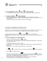
CONNECTING UP TO THE OUTDOOR TEMPERATURE SENSOR.
The control unit can also be fitted with a sensor that monitors outdoor temperature.
The outdoor temperature reading utilised by the control unit may be supplied in one of two different ways:
-
when the outdoor temperature sensor is connected to the boiler the temperature reading is sent from
the boiler to the control unit.
-
when the outdoor temperature sensor is connected directly to the control unit the reading is acquired
and processed by the control unit directly.
If both are present the local sensor is ignored and the outdoor sensor connected to the boiler base is
utilised.
This situation is highlighted by the appearance of error message
E67
.
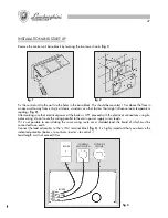
To connect the outdoor sensor to the control unit use the S.EXT connection on the terminal block.
With the outdoor sensor connected, pressing the
key shows the outdoor temperature and heating
water temperature.
●
ENABLING REMOTE OPERATION
The control unit has an input (
TEL
+
and
-
) which allows connection of an optional control unit for distance
operation.
Operating mode:
-
TEL
input open
The control unit operates as described in the handbook.
-
TEL
input closed
The control unit switches to remote mode, that is:
heating and hot water functions enabled, automatic temperature regulation according to timer programme
with on-display information while upper display shows the
TEL
message in place of room temperature.
This mode persists until the user disables it by acting on the remote mode switch (
TEL
input open). Standard
operating mode is then restored.
●
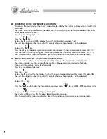
CLOCK SPEED CORRECTION
Allows you to improve clock precision by increasing speed (should it run slow) or decreasing speed
(should it run fast).
The entire correction procedure must be done with the control unit powered and connected to the boiler.
Clock correction:
Press key
R
and keep it pressed.
Press the
H/Day
key
Release the
R
key and wait for the display to show the “
Hour
” confirmation message.
The next two stages must be done within 5 seconds otherwise the procedure will be aborted (a change of
one unit alters clock speed by 30 seconds a year).
Release the
H/day
key.
Press the
+
key to increase clock speed (an increase of one unit speeds up the clock by 30 seconds a year).
Press the
–
key to reduce clock speed (a decrease of one unit slows down the clock by 30 seconds a year).
Wait 5 seconds after the last modification to exit this function and recommence normal operation.
83
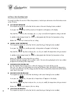
Para programarla presione el botón
; en la pantalla aparecerá la temperatura actualmente
programada.
Manteniendo presionado el botón
, presione los b y - para programar la temperatura
deseada.
Soltando el botón
la programación será memorizada.
●
TEMPERATURA AMBIENTE REDUCIDA
La programación de esta temperatura se realiza con la función “calefacción” o “circ. sanitario/calefacción”
activada.
Para programarla presione el botón
; en la pantalla aparecerá la temperatura actualmente
programada.
Manteniendo presionado el botón
, presione los botones
+
y
-
para programar la temperatura
deseada.
Soltando el botón
la programación será memorizada.
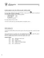
VISUALIZACIÓN DE LOS PARÁMETROS Y ESTADO DE LA CALDERA
Presionando varias veces el botón se pueden visualizar, en la secuencia abajo indicada, los parámetros
principales de la caldera.
Parámetros visualizados:
-
Temperatura efectiva del agua de calefacción (símbolo
intermitente)
-
Temperatura efectiva del agua caliente sanitaria (símbolo
intermitente)
-
Temperatura ambiente programada en base al nivel actual (símbolo
intermitente)
-
Temperatura externa (símbolo
intermitente)
Si no hay una sonda externa la pantalla indica “
—:—
“
-
Presión del agua en la instalación (símbolo
intermitente)
Si no hay un presostato para el agua la pantalla indica “
—:—
“
El símbolo encendido indica que está funcionando el “circ. sanitario” o la “calefacción”.
Summary of Contents for thin 24 MCS W TOP U/IT
Page 3: ......
Page 5: ......
Page 7: ......
Page 9: ......
Page 11: ......
Page 13: ......
Page 15: ......
Page 17: ......
Page 19: ......
Page 21: ......
Page 23: ......
Page 25: ......
Page 27: ......
Page 29: ......
Page 31: ......
Page 33: ......
Page 35: ......
Page 37: ......
Page 39: ......
Page 41: ......
Page 43: ......
Page 45: ......
Page 47: ......


