60
FLUE EXHAUST CONNECTION TO FAN-FORCED DRAUGHT VERSION (B22)
The boiler is envisaged being
connected to a chimney
and/or a flue pipe with the following specification:
●
of being sealed airtight, as with the connection to the chimney itself;
●
of being of suitable material;
●
of being connected within sight;
●
for directional changes use 90
°
and 45
°
bends;
●
of not having any intercepting devices;
●
of having the axis at the entrance of the terminal section perpendicular to the opposite internal wall of the
chimney;
●
of being firmly fixed and sealed at the entrance, without protruding beyond the inner walls of the chimney;
●
of receiving preferably one boiler only;
●
of observing the local regulations in force.
FLUE EXHAUST CONNECTION TO SEALED CHAMBER VERSION (C12-C32-C42)
The boiler is for combustion in a sealed chamber and does not require any special ventilation, it can be
located also in small rooms, lumber-rooms, laboratories. In addition, there are various possibilities for combustion
fumes evacuation and external air intake; basically the boiler is projected for two types of fumes evacuation/
air intake:
●
fumes evacuation/air intake concentric pipes system,
●
fumes evacuation/air intake double pipes system.
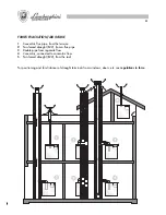
In this way it is possible, by using suitable mounting kits, to connect boiler to concentric flues, ventilating flues,
separate flues, etc.; some possible solutions are indicated on page 61.
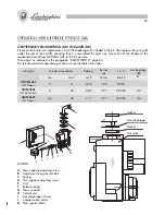
FLUE EXHAUST CONNECTION
Flue pipe
or chimney
YES
NO
77
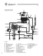
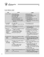
ESQUEMA DE MONTAJE
BM
Bobina modulante
CA
Centralita de arranque Honeywell
CR
Control remoto - termostato ambiente
CiR
Circulador
EC
Electrodo de control
ES
Electrodo de encendido
KA
Termostato anticongelante (a petición)
L
Línea
MAX R
Regulación máx. calefacción
N
Neutro
PF
Presóstato humos
Pma
Presóstato falta agua
PR
Botón de rearme
P.risc.
Potenciómetro circ. calefacción
PS
Presóstato circ. sanitario
P.san.
Potenciómetro circ. sanitario
RA
Resistencia anticongelante (a petición)
RF
Resistencia antiparasitaria
SB
Luz indicadora de bloqueo
SC
Tarjeta conexiones
SR
Sonda circ. calefacción
SRT
Tarjeta RX-TX
SS
Sonda circ. sanitario
SW1
Selector funciones
TIMER
Regulación temporizador caldera
TR1
Transformador
TST
Termostato de seguridad total
V
Válvula 3 vías
VG
Válvula gas
VN
Ventilador
DESCRIPCIÓN
+ -
NOTA:
Averiguar que los
microinterruptores en el
selector
SW1
sean como
indicado en el dibujo
Summary of Contents for thin 24 MCS W TOP U/IT
Page 3: ......
Page 5: ......
Page 7: ......
Page 9: ......
Page 11: ......
Page 13: ......
Page 15: ......
Page 17: ......
Page 19: ......
Page 21: ......
Page 23: ......
Page 25: ......
Page 27: ......
Page 29: ......
Page 31: ......
Page 33: ......
Page 35: ......
Page 37: ......
Page 39: ......
Page 41: ......
Page 43: ......
Page 45: ......
Page 47: ......


