63
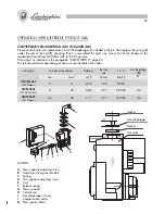
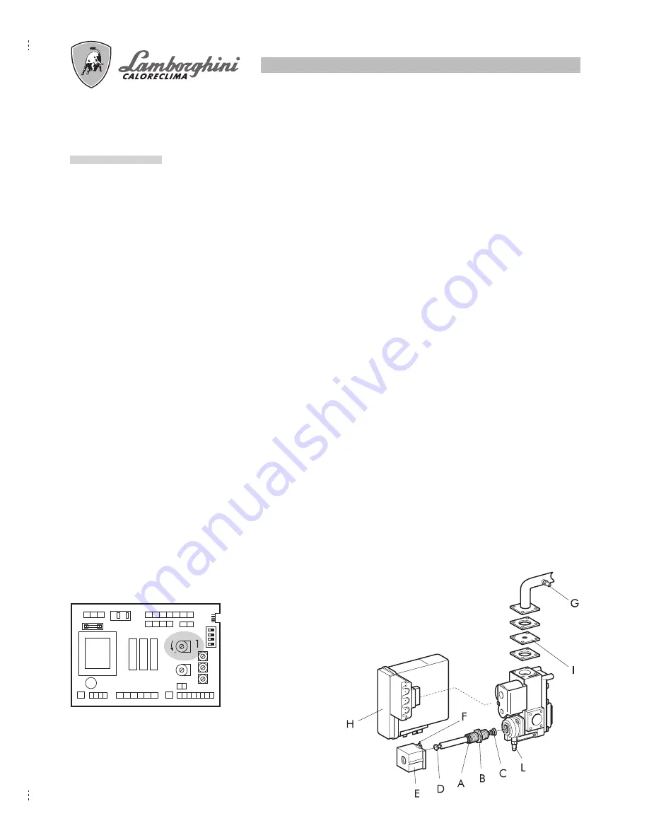
The boiler allows to adapt the heating thermal power (without involving the adjustment of the capacity available
for the production of hot water) to the thermal need of the rooms to be heated.
When leaving the factory all boilers are set to 70% of their maximum output. To adapt the boiler to the thermal
power needed by the plant it is necessary to carry out the following operations:
●
Insert a manometer in the pressure tube (
G
)
●
Electrically feed the gas valve with the boiler on in the WINTER position
●
Adjust the heating potentiometer (
1
) located on the modulation card until the gas pressure required by the
heating system capacity is reached (see pressure curves).
Should it be necessary to adjust the minimum and maximum regulation of the gas valve (preset at the factory)
for the hot water supply, following operations should be carried out:
●
remove the power supply contacts from the coil (
E
).
●
power the gas valve with the boiler on in the SUMMER position and bleed off domestic hot water at the
maximum flow rate (13 litres/min).
●
turn the adjustment screw (
D
) all the way down without using any tools.
●
loosen the locknut (
B
)
●
use a wrench to turn the coil screw (
A
) until maximum gas pressure (values are given on page 43) is
reached.
●
tighten the locknut (
B
).
●
undo the adjustment screw (
D
) until minimum gas pressure (values are given
on page 43) is reached.
●
reconnect the coil (
E
).
This task sets the boiler so that it suits the needs of the user.
NOTE: To carry out this adjustment it is necessary to use a water-column pressure gauge, connecting it to
the pressure outlet (G).
ADJUSTMENTS
LEGEND
A
Max. capacity adjusting screw
B
Adjustment fixing
counter-bolt
C
Spring
D
Min. capacity adjusting
screw
E
Coil
F
Release spring
G
Pressure outlet
H
Control unit
I
Gas diaphragm
(if any)
L
Compensation
outlet
Modulation card
74
Los grupos térmicos salen del establecimiento industrial ya ajustados y preparados para funcionar con GAS NATURAL
y GAS LÍQUIDO. Estos ajustes están realizados sin la conexión del terminal de compensación (Pos. A).
Para efectuar el ajuste véase la tabla representada a continuación:
CURVAS DE PRESIÓN EN EL QUEMADOR - POTENCIA SUMINISTRADA
REGULACIÓN GAS - INYECTORES
Presión en los inyectores mbar
Caudal
Inyectores
quemador
mín.
máx.
m
3
/h
Ø mm.
Tipo de gas
GAS NATURAL
(G20-20mbar)
GAS LIQUIDO B
(G30-28/30mbar)
GAS LIQUIDO P
(G31-37mbar)
2
5
6,2
11
25
32
3,06
0,89
1,17
1,25
0,77
0,77
P.C.I.
kcal/h
8.550
29.330
22.360
A
Terminal de compensación
B
Tubito de conexión
Para efectuar el ajuste de la válvula del
gas procedan de la siguiente manera:
a)
quiten el tubito
B
del terminal
A
;
b)
efectúen el ajuste
c)
vuelvan a conectar el tubito
B
al
terminal
A
.
Summary of Contents for thin 24 MCS W TOP U/IT
Page 3: ......
Page 5: ......
Page 7: ......
Page 9: ......
Page 11: ......
Page 13: ......
Page 15: ......
Page 17: ......
Page 19: ......
Page 21: ......
Page 23: ......
Page 25: ......
Page 27: ......
Page 29: ......
Page 31: ......
Page 33: ......
Page 35: ......
Page 37: ......
Page 39: ......
Page 41: ......
Page 43: ......
Page 45: ......
Page 47: ......

