30
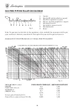
PRESSURE DROP mmH
O
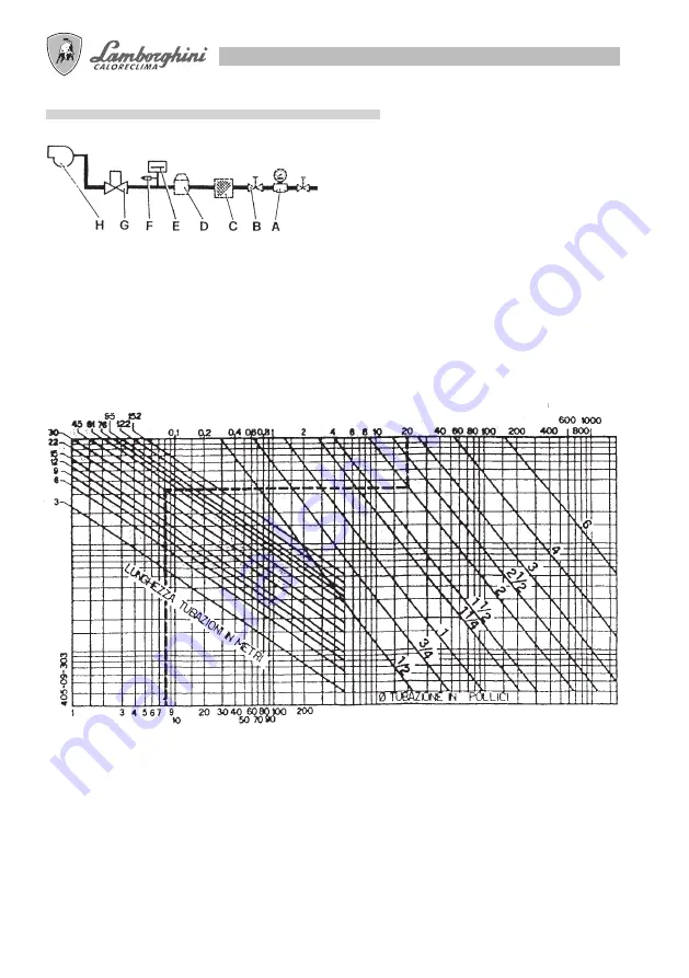
EXAMPLE
FLOW RATE: 0 m
3
/h
DIAMETER: ”
LENGTH: 45 m
Using a gas with density of 0.6
there will be a pressure drop of 8 mmH
GAS FEED PIPE INSTALLATION DIAGRAM
A
Counter
B
Gas shutoff cock (supplied on request)
C Gas filter (supplied on request)
D Pressure regulator (supplied on request)
E
Gas pressure switch
F
Gas outlet on pressure switch
G Gas electrovalve
H Burner
Fig. 5
Note: The gas pipe must conform to the regulations in force and both the accessories and the gas
pipe must have a diameter proportional to the length of the pipe and the gas feed pressure.
DIAGRAM FOR THE DETERMINATION OF THE GAS FEED PIPE DIAMETER
FLOW RATE IN m3/h (NATURAL GAS WITH RELATIVE DENSITY OF 0.6)
Fig. 6
SPECIFIC WEIGHT OF OTHER GASES MULTIPLICATION COEFFICIENT
0,6
,00
0,65
,04
0,7
,08
0,75
,
0,8
,6
0,85
,8


