5
Display off
Press Key
Data Transfer
Wait...
Data Process
Wait...
Change CF
Press Key
(95666) TROPOS
Operating Instructions
Operating Instructions
Data logger TROPOS (95666)
In one of two possibilities the card must be inserted easily.
After insertion of the CF card this indica-
tion appears again after a short while:
To fi nish this menu item the switch has to be rotated.
Display Off
TROPOS can be switched from the
on-line mode
into the
standby mode
by
pressing the push-/ rotary switch when
this indication appears in the display:
TROPOS keeps in the
standby mode
until the push-/ rotary
switch is moved again.
Further indications
TROPOS is busy with saving and
processing of data or settings when
these kinds of indications appear.
TROPOS is blocked in these times for
operations by the push-/ rotary switch.
4.4
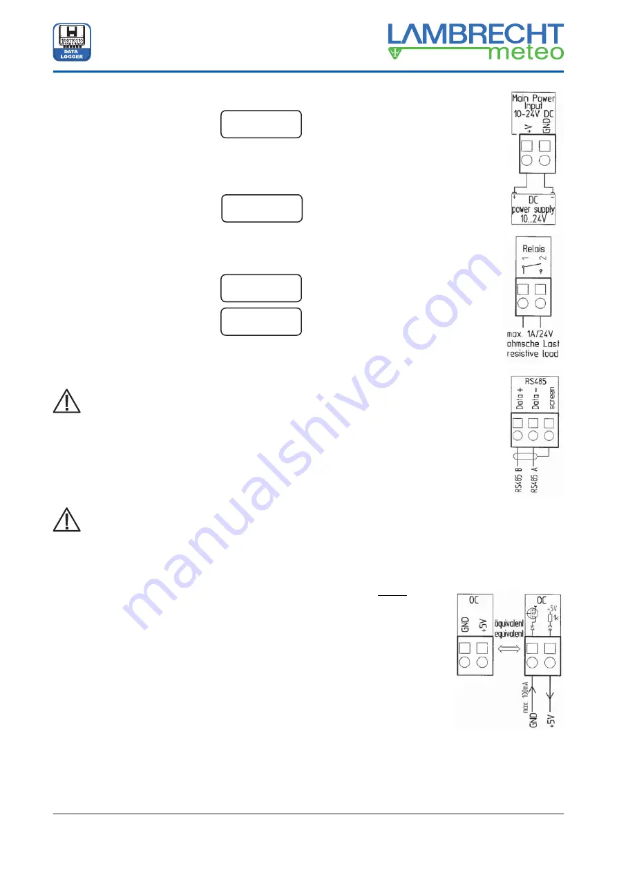
Wiring of the TROPOS ports
Attention! Warranty losing!
Don’t wire during connected power supply!
The supply voltage of TROPOS should be switched off
before the next steps can be carried out.
An incorrect handling can destroy TROPOS and the
warranty claim would be lost!
Notes for the correct cable connection are readable
in the chapter 4.1.
You must pay attention to the correct wiring. Current-
and measuring inputs (or supply- and signal inputs)
must not be interchanged.
TROPOS or the sensors can be destroyed by incor-
rect handling. In this case the claim of warranty must
be rejected!
At delivery TROPOS is unwired normally, if there was no
other order.
Provided that the wiring operations of the power supply and
the sensors have been fi nished according to the chapter
4.1
„Confi guration of TROPOS“
,
the details are described in
the following text.
The software confi guration content has to be adjusted ac-
cordingly.
The wiring drawings of the factory-adjusted sensors are
available after software installation on your hard disk in the
directory: TROPOS_SEN_DOC.
An overview about the necessary documents can be shown
and printed out within “
TROPOS-Commander
” under the menu
item „Setup/ TROPOS confi guration“ by the button
.
A schematic diagram about the inputs and outputs at TROPOS
are shown in the
chapter 7, page 9.
1) Connection of the power supply
• The
“+” pole
from a DC power supply unit
has to be connected to
(V+)
port.
• The
“-” pole
from a DC power supply unit has
to be connected to
(GND)
port.
The DC voltage must be smoothed but not
stabilised. The input is protected against in-
correct polarity and temporary voltage peaks
of approx. 30 V.
2) Connection of the relay
•
The relay switches current of 1 A at max.
24 V with resistive loads.
• Avoid inductive loads to prevent arcing.
3) Connection of the RS485 interface
•
Data+
=
RS485 B
•
Data-
=
RS485 A
•
screen
=
shielding of the cable
“screen” is not connected to the ground of the
power supply!
•
The communication interface RS 485 is an
option. It is visible at the front plate of TRO-
POS in every case, but it is only working when
really built-in.
4) OC, Open Collector or Open-Drain output for output
of precipitation pulses
• The
(GND)
port is connected to ground by a transistor
switch. This output switches positive voltages up to 24 V to
ground.
This output is not protected
against overvoltage and over-
current!
This line (OC/ GND) is used to
send signals, together with the
ground port of the TROPOS
power supply.
• The
(+5 V)
output is permanent-
ly connected to the stabilised
operating voltage of +5 V by
means of a resistor of 1 k
Ω
and
a polarity protection diode.


