


15
o
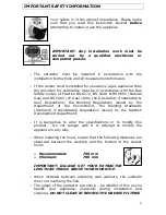
As the colours of the wires in the appliance’s mains lead may not
correspond with the coloured markings identifying the terminals
in your spur box, please proceed as follows:
o
The
blue wire
must be connected to the
terminal marked “N” (neutral), or
black
.
o
The
brown wire
must be connected to the
terminal marked “L” (live), or
red
.
o
The
green/yellow
wire
must
be
connected to the terminal marked “ “
(earth) or
green
.
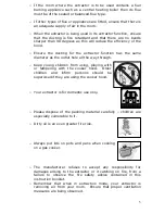
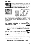
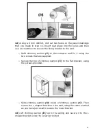
Before beginning installation
o
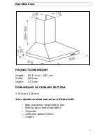
Check that the product purchased is of a suitable size for the
chosen installation area. In addition check whether there is an
electrical socket available that will be accessible once the
extractor is mounted. If the product is going to be used in
extraction mode, then there should also be space to connect a
ducting hose to the outside.
o
Carry out all necessary masonry work prior to the fitting of the
extractor.
o
Ensure that all electrical connections are carried out by a suitably
qualified person.
o
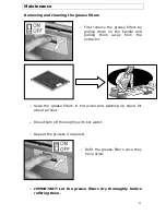
Before commencing installation of the extractor the grease filters
should be removed.
o
Check inside the product and insure that there is no transit
packaging or any other materials, such as packets of screws,
guarantees etc. These should be removed and kept for future
use.
o
If possible, disconnect and move freestanding or slot-in cookers
from their position, to provide easier access to the rear wall and
ceiling. If this is not possible, then a thick, protective covering
should be placed over the worktop, hob top or cooker. This will
help to protect these surfaces from damage and debris.
o
Select a flat surface for assembling the extractor. Cover that
surface with a protective covering and place all parts and fittings
on to it.
o
Rawl plugs are provided to secure the extractor to most types of
walls and ceilings. However a qualified technician must verify the
suitability of the materials, in accordance with the type of wall
Summary of Contents for HJA2480
Page 24: ...24 Your Guarantee...
Page 25: ...25...
Page 26: ...26...
Page 27: ...27...
Page 28: ...28...


