background image

7

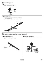
(①)

Bracket

(①)

Holder

Upper roller

Remove

Leading edge

Trailing edge

Door (Trailing edge)

32

64

Upper track

Floor guide S

*

Pan head tapping

screw 5×40

(Attached to

)

Upper roller

Upper stopper

Upper track

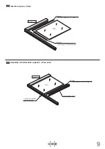
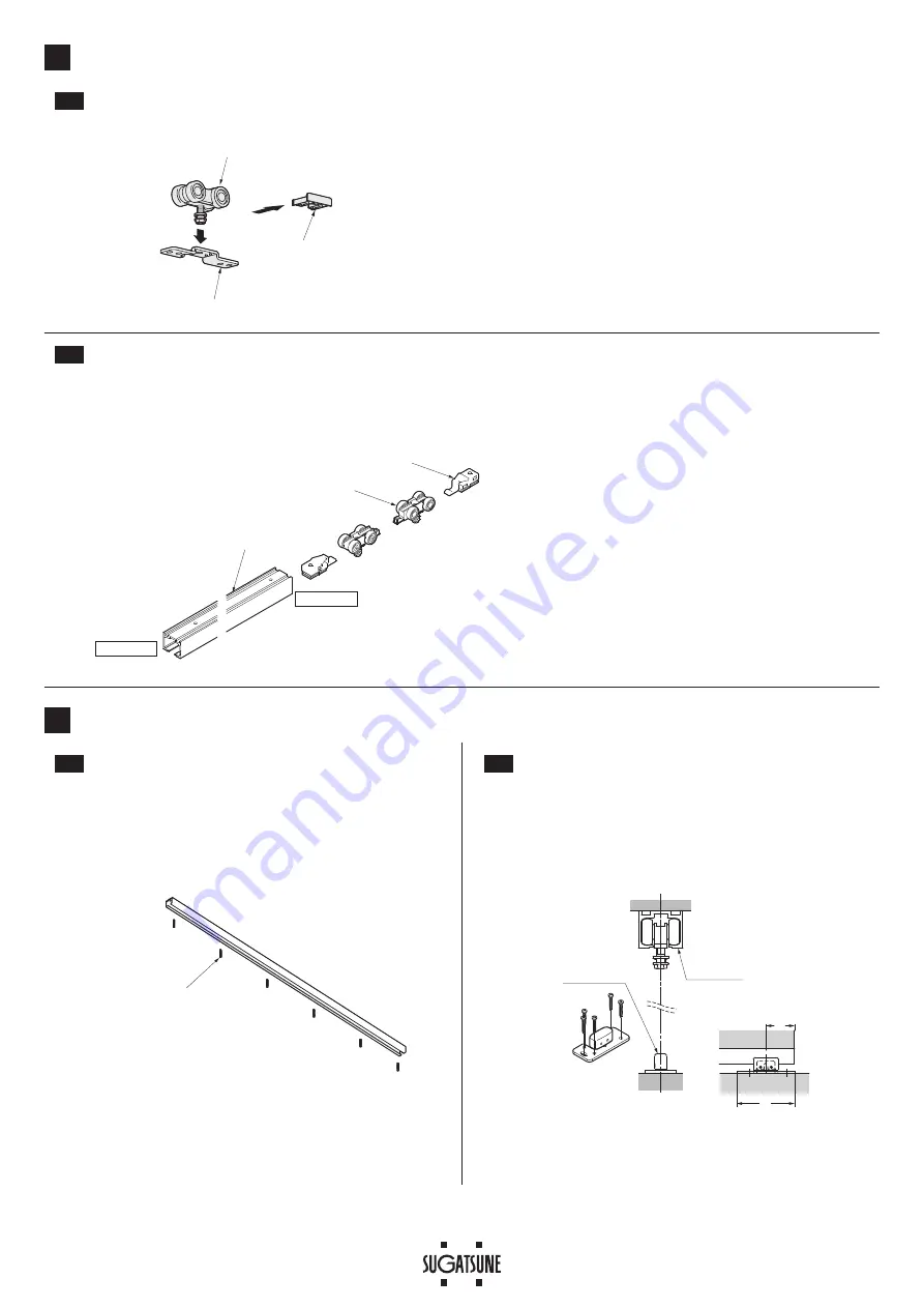
Assembling parts

2-1


Disassembling Upper rollers

Remove Upper roller bracket and holder

2

2-2


Assembling parts

(1)   Insert into the track two Upper roller

 and Upper stopper

 in the 

order shown in below figure.

(2) Tape around rollers and upper track to prevent drop of inserted parts.

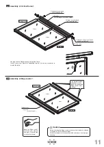
Installing Upper track

 and Floor guide S

3-1


Installing Upper track

Confirm that leading edge of the upper track is in same direction as 
the leading edge of the door.
Fix the upper track with attached screws 5×40.

3-2


Installing Floor guide S

Install the Floor guide so that it stays under the door when it is 
opened or closed.

3

*   

Bind head tapping 

screw 4×16

Summary of Contents for FD80-AFH

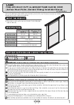
Page 1: ...ening closing the door A frame with poor strength might result in improper and slower movement of the door In the worst case the door might drop down and cause injury Do not try to use this product fo...

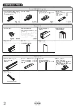
Page 2: ...ket countersunk head screw M4 x 25 8 pcs for Corner Part Horizontal frame 2000 mm Vertical frame 2500 mm 3000 mm Upper track Various sizes Accessory screw Pan head tapping screws 5 40 Gasket for 5 mm...

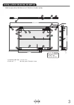
Page 3: ...00 19 60 18 32 2 5 5 additionaol When door jumb is not prorided apply Two way soft closer CAUTION 9 5 3 5 2 5 11 8 1 7 4 5 8 12 1 13 12 2 10 11 5 10 3 7 5 INSTALLATION DRAWING EXAMPLE 1 Height adjusta...

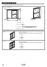
Page 4: ...r of glass panels GW Glass width DW 34 DH Door height FH 64 Cut off after the decimal point for the divided dimensions Example 2 Example 1 Ex 1 door on single track Size of each door when Opening widt...

Page 5: ...50 Thickness of Vertical frame x 2 1 3 Cutting and hole processing of Intermediate support when used Cut carefully so the cut edge is square to avoid bias and skewing Make sure to remove any burr Als...

Page 6: ...pth 20 mm 2 holes at each end 1 4 Processing of Vertical frame Step 1 1 5 Processing of Vertical frame Step 2 Drill holes according to the quantity of Intermediate support Hole A only if there is no I...

Page 7: ...into the track two Upper roller and Upper stopper in the order shown in below figure 2 Tape around rollers and upper track to prevent drop of inserted parts Installing Upper track and Floor guide S 3...

Page 8: ...ead screw M4 x 25 Hexagon socket head cap screw M6 x 30 Vertical frame 4 1 Preparation of Horizontal frame Upper Assembling door 4 Set the Bracket to upper Horizontal frame using Plate nut The distanc...

Page 9: ...50 Vertical length GH Glass height Glass Bottom side Glass Gasket Horizontal length DW Door width 50 Hexagon socket head cap screw M4 x 30 Intermediate support Bottom side 4 3 Insertion of glass Step...

Page 10: ...ngth DW Door width 50 Hexagon socket head cap screw M6 x 30 Corner part Horizontal frame upper Hexagon socket countersunk head screw M4 x 25 Top side Bottom side 4 5 Insertion of glass Step 2 when Int...

Page 11: ...er from shifting Top side Bottom side Spatel 4 7 Assembly of Vertical frame Bend the Edge cover between your fingers and press it into the side of the Vertical frame 4 8 Assembly of Edge covers You ma...

Page 12: ...be hanged Tilt the door as shown in the figure and set the Floor guide S to the groove of the bottom Horizontal frame 2 Push the door and set the hanger bolts as shown in the figure below 1 2 2 2 Be...

Page 13: ...lder as shown below 3 After adjusting the door pull the wrench at a right angle away from the door Make sure the width across flats of the bolt head is as shown in the figure Adjustment of door height...

Page 14: ...the track and pull out the roller Then clean the roller Check for loose screws retaining the upper track Tighten the screw Heavy door operation Check if door bottom contacts with floor Confirm that t...

Reviews: