Insert the gasket
④
in the lock body
①
so that it will
be located on the outer side of the cabinet. Then
fi t the lock body on the glass door and fasten fi xing
screws
③.
Insert the gasket
④
in the strike plate
②
so that it will
be located on the outer side of the cabinet. Then,
fit the strike plate on the glass door and fasten fixing
screws
③
.
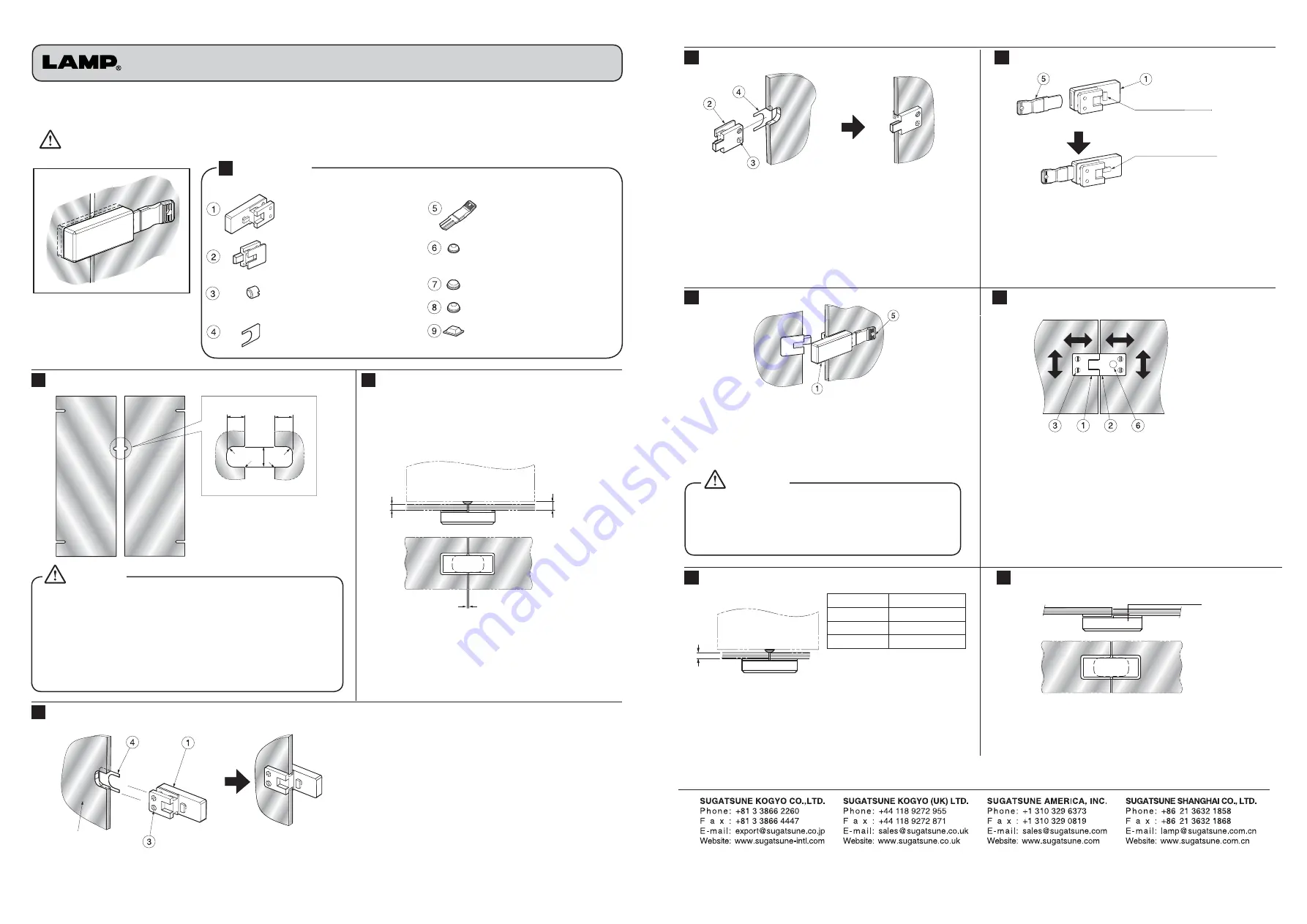
XL-GC01 Double Door Lock Installation Manual
PAT
• Maximum door size is W500 mm x H1200 mm.
(1)
• Maximum door weight is 12kg.
(1)
• Applicable glass thickness is 5,6 or 8mm.
• Should you have any question with regards to the glass cut out,
please contact your local glass supplier.
(1)
Only applies when using in combination with XL-GC07 hinge.
Glass Processing
Lock Installation Position
1
Lock Body Assembly
2
Strike Plate Assembly
3
Locking Opertaion
…
Lock Body ×1
…
Strike Plate ×1
…
Fixing Screw ×4
…
Gasket ×2
Left
Glass Door
Right
Glass Door
23.5
R8
20.5
C1
20.5
R8
C1
5,6,8mm
Left
Glass Door
Right
Glass Door
12
2
Rotor is vertical when
key is not inserted
Rotor is horizontal
when key is inserted
Left
Glass Door
Right
Glass Door
Caution
Caution
Top view
Front view
…
Clear Bumper BS-12 ×1
…
Clear Bumper BS-6 ×2
…
Clear Bumper BS-2 ×2
…
Clear Bumper BS-32 ×2
…
Key ×2
4
Key Operation
5
Lock Alignment
Door Thickness
Bumpers
(
T
)
5
mm
⑦
BS-6
(
6.2
)
6
mm
⑧
BS-2
(
5
)
8
mm
⑨
BS-32
(
3.1
)
Right Glass Door
Left
Glass Door
Top and Bottom Panel
5~ 8
ISO9001(Japan Offices and Sugatsune America) and ISO14001(Chiba Production division and Logistic center), certified.
eft
lass Door
Right
Glass Door
less than 0.7mm
6
Bumpers
6
7
Door Alignment
Before installation, please be sure to confirm all parts are contained in package.
Parts List
Thank you for purchasing the XL-GC01 Double Door Lock. In order to insure the best possible
installation, we recommend that you read the following instructions closely.
Mishandling or wrong installation of this product may lead to injury.
Always clear the working area of any hazardous object before proceeding with the installation.
To ensure a smooth operation of the lock, align lock body
①
and strike plate
②
both vertically and horizontally by
loosening the fi xing screws
③
on the back side. Adjustment
range is 2 mm vertically and 1mm horizontally.
Affi x clear bumper BS-12
⑥
on the rear of strike plate
②
a shown above in order to prevent scratches to the body
surface when the right door is closed before the left one.
Insert key
⑤
in the slot of the lock body
①
as shown
above in order to unlock. Simply remove the key
⑤
in
order to lock. We recommend that you test the good
operation of the rotor before proceeding to the fi nal
adjustments.
Make sure to insert key
⑤
into the slot of the lock
body
①
, before closing the doors for the lock
adjustment.
For smooth operation, we recommend to make sure
of the doors parallelism. Moreover both doors depth
alignment should be maintained within 0.7mm as
shown above.
Always insert the key
⑤
into the slot of the body lock
①
before closing the door. Failure to do so may
result in damage to the lock.
Affi x clear bumper
⑦
,
⑧
or
⑨
to the top and
bottom of both doors, where the glass makes
contact with the cabinet body. The clear bumper size
should be selected according to the glass thickness
as shown in the table above.
Inside view
Outside view
Inside view
Caution
Inside view


