LAMP XL-MT120-U01/02 Strike
Case for Door Latch
PAT
Installation Instructions
Please read this instruction sheet carefully for proper installation and operation.
Incorrect installation and improper use of the product may cause damage to the unit, and also cause injury.
This instruction sheet should be kept by the user after installation.
Parts
Make sure that the correct parts have been provided. The model number is XL-MT120-U02
(left hand use).
XL-MT120-U01 (right hand use) is also available.
Applicable thickness:
8
,
13 mm
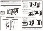
Cutout Drawing
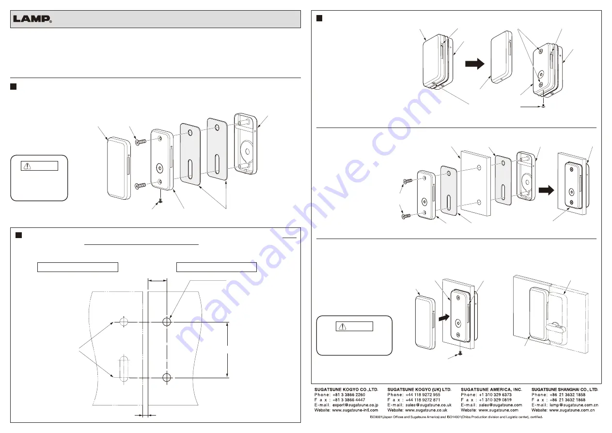
Referring to the below drawing, make cuts for the strike so that it becomes at the
same level as the cuts for the glass door latch.
For the cutout drawing of the glass door latch, refer to the installation manual of the
glass door latch (XL-MT120-H).
Step 1. Remove the rear cover
1. Unscrew the rear cover
fixing screw at the bottom
of the cover.
2. Push the release pins at
both sides of the rear
cover in, one pin at a time,
and remove the rear cover.
3. Separate the front and
back plates from each
other by unscrewing the
fixing screws of the back
plate.
Caution
Rear cover
Front plate
Fixing screw
Rear cover fixing screw
※
Back plate
Spacer
30.5
2
×
φ
13mm holes
Maximum 2.5 mm
90
Same level
Cutout drawing for the latch
Cutout drawing of the strike
Installation Procedure
Rear cover
Release pin
Fixing screws
Release pin
Front plate
Front plate
Rear cover
Back plate
Rear cover fixing screw
Step 2. Attach the strike case to the door
1. Sandwich the glass door
with the front and back
plates.
2. Insert the spacer between
each of the front and back
plates and the glass door,
fix the strike case with the
fixing screws from the
back plate side.
Fixing
screw
door
Spacer
Front plate
Front plate
Back plate
Back plate
Spacer
Step 3. Attach the rear cover
Reverse procedure to remove the rear cover.
1. Attach the rear cover to
the back plate. Be sure to
set it one side at a time,
pushing the release pin in.
2. Tighten the rear cover fixing
screw from the bottom.
The figure to the right shows
a glass door latch with the
hook latched.
Caution
After fixing the rear cover, make
sure that the release pin has
become in original position.
Back plate
Release pin
Rear cover
Rear cover fixing screw
Latch
(XL-MT120-H02)
Strike case
(XL-MT120-U02)
This product is trial
fitted. Please
disassemble before
installation.
2013.02 PRINTED IN JAPAN 0145-2


