Contents:
Air Horn Amplifiier
1
Two Way Switch
1
Momentary Switch
1
Bracket for Switch
1
Mounting Accessories
1
Fuse(s)
1
Wiring:
WARNING! All customer supplied wires that connect to the positive terminal of
the battery must be sized to supply at least 125% of the maximum operating
current and FUSED at the battery to carry that load. DO NOT USE CIRCUIT
BREAKERS WITH THIS PRODUCT!
RED
- To 9 - 30V DC Power Source
WHITE 1
- To Speaker
BLACK
- To Chassis Ground
WHITE 2
- To Speaker
YELLOW
- Positive Power Input to Trigger Air Horn
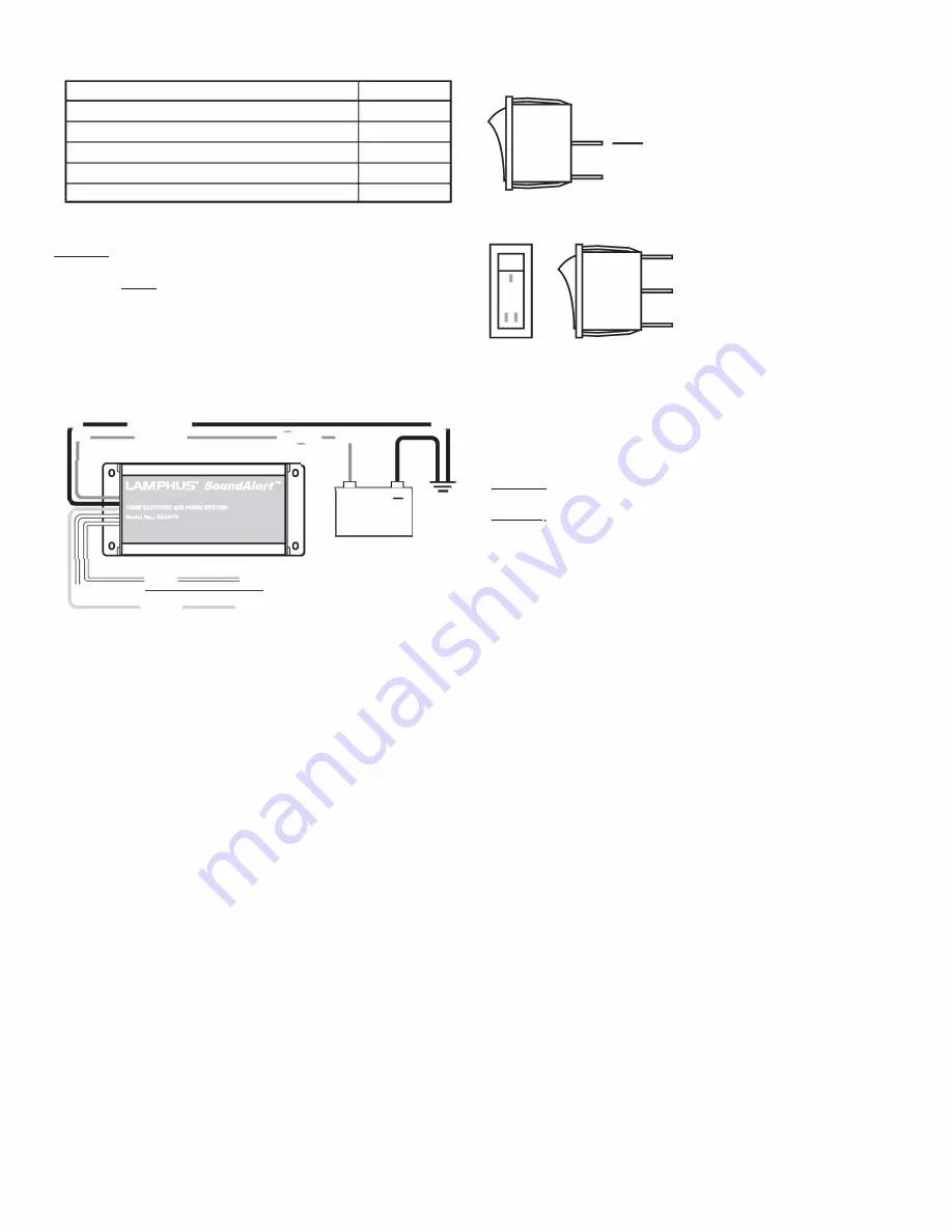
Wiring Diagram:
�--------BLACK .. ----------------------------------....
,-����
RED
�������""'�,-.� ......
WHITE
=====
n111 SPEAKER
'=====WHITE
Ll.J
YELLOW
SWITCH
Operating Air Horn with Momentary Switch
+
BATIERY
GROUND
1.
Connect the center pin of the momentary switch to a positive power source. Be
sure to utilize an in-line fuse (customer supplied) if connecting the momentary
switch directly to the positive post of the battery.
2. Connect the outer pin of the momentary switch to the YELLOW wire on the air horn
amplifier.
3. Refer to Wiring Diagram Momentary Switch if you wish to activate the air horn
through the included momentary switch.
Operating Air Horn with Vehlcle Horn Button
Note: Hands free activation of the horn relay refers to using the vehicle's factory
horn button located on the steering wheel to activate the air horn amplifier.
The use of the two-way switch allows the driver to toggle between the
regular vehlcle horn and the air horn. This hands free option can only be
setup on vehicles with positive triggered horn relay, and would require a
relay or other equipment for it to work on negative triggered systems.
1. Locate the wire connecting the vehicle horn button on the steering wheel to the
vehicle horn relay.
2. Cut the wire.
3. Connect the wire on the vehicle horn relay side to one of the outer pins on the
two-way switch.
4. Connect the wire on the vehicle horn button side to the middle pin on the two-way
switch.
5. Connect the remainder outer pin on the two-way switch to the YELLOW wire on the
air horn amplifier.
6. Refer to Wiring Diagram Hands Free if you wish to activate the air horn through the
factory horn button on the steering wheel.
Wiring Diagram Momentary Switch:
Positive Power In
-- YELLOW wire on air horn amp
Wiring Diagram Hands Free:
-- Connect to vehicle horn relay
-- Connect to vehicle horn button
-- YELLOW wire on air horn amp
Mounting:
The air horn ampllfler Is designed to be mounted Inside the engine bay around
the battery's vicinity. The air horn amplifier is waterproof and can be mounted
to an area exposed to the elements if necessary. If mounting the amplifier to an
area exposed to the elements, be sure that all wiring connection and ln-llne
fuse holder are made waterproof by using dielectric grease, liquid electrical
tape, or via other means.
WARNING! Make sure NOT to mount the air horn ampllfler In the deployment of
any air bag. Refer to the air bag warning on the first page of this manual.
CAUTION! Permanent mounting of this product will require drilling. It is
absolutely necessary to make sure that no other vehicle components could be
damaged by this process. Check both sides of the mounting surface before
starting. If damage is likely, select a different mounting location.
Mounting of Air Horn Amplifier:
1. Position the air horn amplifier against the desired mounting location.
2. Scribe the area where the mounting holes would be drilled.
3. Proceed to drilling of the surface for the mounting screws. Make sure no vehicle
component could be damaged during this process.
4. Secure the air horn amplifier to the mounting surface with the included screws.
Mounting of Switch:
1. Position the bracket for switch against the desired mounting location.
2. Scribe the area where the mounting holes would be drilled if the bracket is to be
permanently mounted, otherwise utilize the included double sided tape.
3. Proceed to drilling of the surface for the mounting screw. Make sure no vehicle
component could be damaged during this process.
4. Secure the bracket for switch to the mounting surface with the included screws.
5. Install the switch of choice into the bracket for switch.
Specifications:
Input Voltage: 9 - 30 V DC
lnputCurrent:4.31 AMPS Max.@ 12VDC
Speaker Impedance: 8 OHMS Min.
Output Power:@ 12VDC @BOHMS 100WATIS Max.
Online LED Store S2B Inc. ©2016 All Rights Reserved
Summary of Contents for SoundAlert SAAH75
Page 1: ......


