16
100% GEOTHERMAL HEAT
16
INSTALLER MANUAL
4.1.4. Space requirements
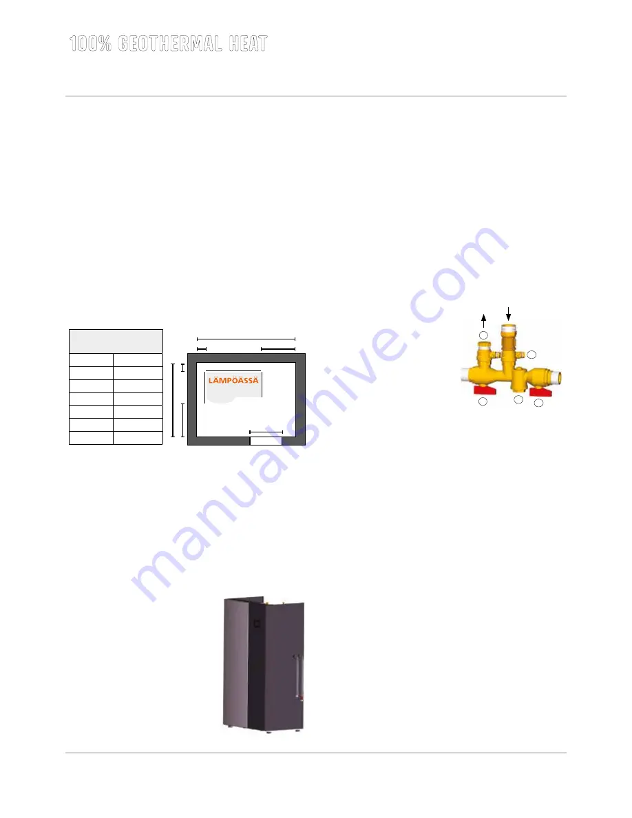
A Lämpöässä Vmi ground source heat pump can conveniently be placed
into a technical or utility room. The floor space to be reserved for the
machine needs not significantly exceed its external dimensions. Approx.
50-60 cm of installation room should be reserved on the respective side
for lateral ground circuit connections. Considering possible equipment
maintenance, there must be approx. 70 cm of free space in front of the
geothermal heat pump.
The height of a Lämpöässä Vmi series ground source heat pump (includ
-
ing adjustable feet) is at least 183 cm. The transport platform adds some
8 cm. Approx. 30 cm of free space must be reserved for connections on
top of the machine. This should be kept in mind when installing the equip
-
ment into a low room, such as basement.
4.2. HVAC installation
4.2.1. Heat collection circuit and fill group installation
On the right side of the ground source heat pump there are entry points
for heat collection circuit hoses. Install the flexible supply (1) and return
(2) hoses included in the accessory package into the heat collection pip
-
ing. See picture. Attach the shut-off valve included in the accessory pack
-
age to the end of the rear hose. The hoses
and joints must be sealed carefully.
If cooling equipment located higher than
the ground source heat pump is connected
to the pump, a membrane expansion ves
-
sel must be included in the system. In
such cases, a de-aeration connection must
be installed to the highest point of the
system and the fill container removed from
use by closing the shut-off valve under
-
neath it.
Vmi 6 – 17 space
requirements (mm)
A
50
B
50
C
500
O
700
X
1570
F
700
Y
1420
B
A
X
Y
F
C
O
670,8
1020
700
4.2.2. Filling and de-aeration of the heat collection circuit
Accessories required for the filling and de-aeration of the ground circuit:
•
mixing tank, 60 litres
•
submersible pump fitted with a filter, lifting height approx. 30m
•
water/ethanol or water/glycol mixture (1:1) with a frost
resistance of -16 °C
•
reinforced hose 1” (2 pc.), length approx. 3 m
•
connector 3/4” (female thread) for reinforced hose
•
connector 1” (female thread) for reinforced hose
WORK STAGES
Please check that the ground circuit
has been correctly connected.
1. Remove the styrox packaging
protecting the group of fill
valves.
2. Detach the expansion vessel
from the foremost ball valve.
3. The foremost shut-off valve (2)
of the group of fill valves must
always be open.
4. Attach the submersible pump textile hose to the foremost ball valve
(3) in the group of fill valves and open the ball valve.
5. Attach a reinforced hose from the ball valve (4) at the back of the
group of fill valves to the fill container and open the valve.
NOTE! The flow direction has to be correct since there is a one
way valve installed between the cooling connections.
6. Fill the container with water/ethanol or water/glycol (frost r.
7. Bleed air from fill hoses by activating the submersible pump and
keeping the valve (1) open. When air has escaped, close the valve
(1) to start actual fluid circulation through the ground circuit.
8. Add fluid until the piping is full. Upon de-aeration, the unit’s own
brine circulation pump can be used to speed up fluid circulation.
•
Check that the motor protection switch (QM1) is not on.
•
Turn master switch (Q1) and control current switch (F10) on.
•
The forced control of gound circuit pump can be activated
from the maintenance manual of ÄssäControl. Go to manual
control and choose manual control on and ground circuit 1
on.
NOTE
! When using the system’s own brine circulation pump for
de-aeration purposes, check that the flow direction of the separate
submersible pump is always the same as that of the unit’s pump.
9. Keep the submersible pump running until the fluid is clear and no
gurgling can be heard from the pipes. NOTE! De-aeration usually
takes several hours and helps to ensure that all the air is remove
from the system and will not cause any malfunctions once the
system is started. Leave no pressure in the network! Remove any
air from the evaporator through the de-aeration connection of the
pipe located between the ground circuit and the evaporator.
1
2
4
5
3
-16 °C) mixture (ratio 1:1).
1. 2.
Summary of Contents for VMI 6-17
Page 1: ...L MP SS Vmi 6 17 L MP SS 3 2016 INSTRUCTIONS FOR USE INSTALLATION AND MAINTENANCE...
Page 31: ...XL 2015 811 2013 A A A B C D E F G A A A B C D E F G Vmi 6 38 dB 00 dB 8 kW 8 kW 8 kW...
Page 32: ...A A A A A A A A B C D E F G A A A A B C D E F G XL 2015 811 2013 XL X Vmi 6...
Page 35: ...XL 2015 811 2013 A A A B C D E F G A A A B C D E F G Vmi 9 41 dB 00 dB 10 kW 10 kW 10 kW...
Page 36: ...A A A A A A A A B C D E F G A A A A B C D E F G XL 2015 811 2013 XL X Vmi 9...
Page 39: ...XL 2015 811 2013 A A A B C D E F G A A A B C D E F G Vmi 11 36 dB 00 dB 11 kW 11 kW 11 kW...
Page 40: ...A A A A A A A A B C D E F G A A A A B C D E F G XL 2015 811 2013 XL X Vmi 11...
Page 44: ...A A A A A A A A B C D E F G A A A A B C D E F G XL 2015 811 2013 XL X Vmi 11 1x230V...
Page 47: ...XL 2015 811 2013 A A A B C D E F G A A A B C D E F G Vmi 14 38 dB 00 dB 14 kW 14 kW 14 kW...
Page 48: ...A A A A A A A A B C D E F G A A A A B C D E F G XL 2015 811 2013 XL X Vmi 14...
Page 52: ...A A A A A A A A B C D E F G A A A A B C D E F G XL 2015 811 2013 XL X Vmi 14 1x230V...
Page 55: ...XL 2015 811 2013 A A A B C D E F G A A A B C D E F G Vmi 17 42 dB 00 dB 17 kW 17 kW 17 kW...
Page 56: ...A A A A A A A A B C D E F G A A A A B C D E F G XL 2015 811 2013 XL X Vmi 17...
Page 60: ......
Page 61: ......
Page 62: ......
Page 63: ......
Page 64: ......
Page 65: ......
Page 66: ......
Page 67: ......
Page 68: ......
Page 69: ......
Page 70: ......
Page 71: ......
Page 72: ......
Page 73: ......
Page 74: ......
Page 75: ......
Page 76: ......
Page 77: ......
Page 78: ......
Page 79: ......
Page 80: ......
Page 81: ......
Page 82: ......
Page 83: ......
Page 84: ......
Page 85: ......
Page 86: ......
Page 87: ......
Page 88: ......
Page 89: ......
Page 90: ......
Page 91: ......
Page 92: ......


