18
100% GEOTHERMAL HEAT
18
INSTALLER MANUAL
The storage tank is to be filled with special care through the group of fill
valves included in the system so that the storage tank pressure never
exceeds 1.5 bar. While filling the storage tank, the air inside it must be
allowed to escape freely and not through air valve or safety valve, for
example. Suomen Lämpöpumpputekniikka Oy cannot be held respon
-
sible for any expenses resulting from storage tank breakage in situations
where the tank has not been filled with water pursuant to the above
instructions.
NOTE! Maximum storage tank pressure is 1.5 bar!
The pipes in the heating network are connected to the ground source heat
pump using either textile hoses (network of radiators) or using a fixed
piping network (floor heating). These connections prevent sound from
passing into the network. All heating connections (for example, a heating
radiator for an air conditioner or a heated towel rail) must be made to the
heat distribution circuits, not domestic hot water. When the network pip
-
ing is in place, filling may commence.
Storage tank and heating system filling and de-aeration
There must be a de-aeration valve in the same branch with the group of
fill valves. The expansion vessel may be in the same branch as well. The
pipes in the network are filled with water. Note! If renovating, ensure that
the heat distribution piping has been properly rinsed before connecting the
geothermal heat pump.
Filling and de-aerating a heating system fitted with a pressure gauge:
•
Open the fill valve on the heating network.
•
Fill the network with water.
•
De-aerate the storage tank and network until all the air has been
removed and leave the pressure at 1-1.2 bar (max. 1.5 bar).
•
Maximum pressures:
•
Heating network storage tank – 1.5 bar
•
Domestic hot water circuit – 9 bar
Domestic hot water connections and circulation of water
If there is no domestic hot water circulation at the site, make connections
pursuant to HVAC diagrams annexed to these instructions. Domestic
water is connected to the ground source heat pump pursuant to the pic
-
ture in Section 4.2.3. The same picture is provided on top of the unit. The
mixing valve is fitted to the hot water pipe in order to prevent burns. The
overflow pipe is joined to the floor drain as instructed or to an overflow
funnel if the distance to the floor drain is more than two metres. The
overflow funnel must be directed down towards the floor drain. The back
-
pressure valve is fitted to the cold water joint on the input side. See the
annexed HVAC connections diagram.
If DHW circulation is installed to the system should circulation pump to
be installed to the DHW return pipe. DHW coil in the model Vmi has two
seperate sections. When there is no water consumption temperature level
of the circulation is maintained by circulating water only in the upper tank
coil. This avoids mixing of the temperature levels inside a tank. In a nor
-
mal circumstances coils are connected to copper coil which is located on
a roof of the heat pump. When installing DHW circulation ½” plug –
visible in the picture below – will be removed and all connections are
implemented according the HVAC scheme.
If there is domestic hot water circulation at the site, install the water cir
-
culation pump to the domestic water line returning to the heat pump. In
case of the Vmi series, the domestic hot water coil has been divided into
two parts. If there is no domestic water consumption, the coil temperature
level is maintained by circulating water only in the upper storage tank coil.
This way, blending of storage tank temperature stratifications is avoided.
Under normal circumstances, the coils are connected using a copper
elbow located on top of the heat pump. The elbow is cut and connections
made according to the annexed HVAC diagram.
If the ground source heat pump is located far from the building heated or
if heat losses are exceptionally high, for the purposes of optimal ground
source heat pump operation, we recommend installation of a small addi
-
tional heat source (e.g., ÄssäStream heating convector or approx. 20-30 l
electric water heater).
NOTE! External radiators or dryers may not be connected to domestic hot
water circulation!
4.2.4. HVAC checklist
Check that
•
the joints are tight and there are no leaking valves
•
the expansion vessel on the heating system and fill side is
properly installed
•
the overflow pipe on the safety valve and the pressure gauge on
the heating system have been properly installed
Summary of Contents for VMI 6-17
Page 1: ...L MP SS Vmi 6 17 L MP SS 3 2016 INSTRUCTIONS FOR USE INSTALLATION AND MAINTENANCE...
Page 31: ...XL 2015 811 2013 A A A B C D E F G A A A B C D E F G Vmi 6 38 dB 00 dB 8 kW 8 kW 8 kW...
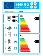
Page 32: ...A A A A A A A A B C D E F G A A A A B C D E F G XL 2015 811 2013 XL X Vmi 6...
Page 35: ...XL 2015 811 2013 A A A B C D E F G A A A B C D E F G Vmi 9 41 dB 00 dB 10 kW 10 kW 10 kW...
Page 36: ...A A A A A A A A B C D E F G A A A A B C D E F G XL 2015 811 2013 XL X Vmi 9...
Page 39: ...XL 2015 811 2013 A A A B C D E F G A A A B C D E F G Vmi 11 36 dB 00 dB 11 kW 11 kW 11 kW...
Page 40: ...A A A A A A A A B C D E F G A A A A B C D E F G XL 2015 811 2013 XL X Vmi 11...
Page 44: ...A A A A A A A A B C D E F G A A A A B C D E F G XL 2015 811 2013 XL X Vmi 11 1x230V...
Page 47: ...XL 2015 811 2013 A A A B C D E F G A A A B C D E F G Vmi 14 38 dB 00 dB 14 kW 14 kW 14 kW...
Page 48: ...A A A A A A A A B C D E F G A A A A B C D E F G XL 2015 811 2013 XL X Vmi 14...
Page 52: ...A A A A A A A A B C D E F G A A A A B C D E F G XL 2015 811 2013 XL X Vmi 14 1x230V...
Page 55: ...XL 2015 811 2013 A A A B C D E F G A A A B C D E F G Vmi 17 42 dB 00 dB 17 kW 17 kW 17 kW...
Page 56: ...A A A A A A A A B C D E F G A A A A B C D E F G XL 2015 811 2013 XL X Vmi 17...
Page 60: ......
Page 61: ......
Page 62: ......
Page 63: ......
Page 64: ......
Page 65: ......
Page 66: ......
Page 67: ......
Page 68: ......
Page 69: ......
Page 70: ......
Page 71: ......
Page 72: ......
Page 73: ......
Page 74: ......
Page 75: ......
Page 76: ......
Page 77: ......
Page 78: ......
Page 79: ......
Page 80: ......
Page 81: ......
Page 82: ......
Page 83: ......
Page 84: ......
Page 85: ......
Page 86: ......
Page 87: ......
Page 88: ......
Page 89: ......
Page 90: ......
Page 91: ......
Page 92: ......


