background image

22

100% GEOTHERMAL HEAT

22

MAINTENANCE MANUAL

Use the button in the bottom left corner to return to the home screen. Use the arrow button in the bottom right corner to return to previous screen.  

For instructions screen, press the ‘i’ button in the top right corner. In case of operation faults, an alarm button is displayed on the top bar.

The system does 
not produce enough 
heat.

A sudden drop in outdoor 
temperature may temporari

-

ly cause inadequate heating 
power in new buildings, 
because moisture contained 
in the structure takes up a 
lot of heat when it dries.

No action required.

During the first year, the 
ground circuit may not 
produce heat at full power 
because the earth around 
the ground circuit pipes has 
not yet become more solid.

No action required.

In the Measurements 
screen, the set value 
and measured value 
do not match.

Some active correction 
function (for example, timer 
or home/away) is adjusting 
the original set value.

The active correction func

-

tion can be deactivated, if 
required.

A spiking over-voltage caus

-

ed by a lightning strike has 
caused a fault in the regu

-

lator (not under warranty), 
causing the temperature to 
drop from the actual values.

Replace the regulator (not 
under warranty).

The regulator motor has 
been set on manual and 
the regulation does not take 
place.

Return the heat distribution 
circuit adjustment motor to 
automatic mode.

In summer, when the 
building indoor temperature 
exceeds the value adjusted, 
the supply water tempera

-

ture sensor indicates higher 
readings as compared to the 
adjustment curve, due to 
rise in the heat distribution 
circuit temperature.

No action required.

The compressor is 
on all the time or for 
long periods of time.

A lot of heat is needed, for 
example the outdoor tem

-

perature is very low or the 
structure is drying during 
the first year’s use of the 
building.

No action required.

Lack of refrigerant. Can be 
detected from bubbles in 
the liquid container even 
after some minutes of use.

Contact a refrigeration supp

-

lier or maintenance

If these instructions do not help, please contact the equipment installer 
or your local dealer. If necessary, contact the Lämpöässä maintenance 
call centre at +358 40 841 8340.

5.3. Alarms

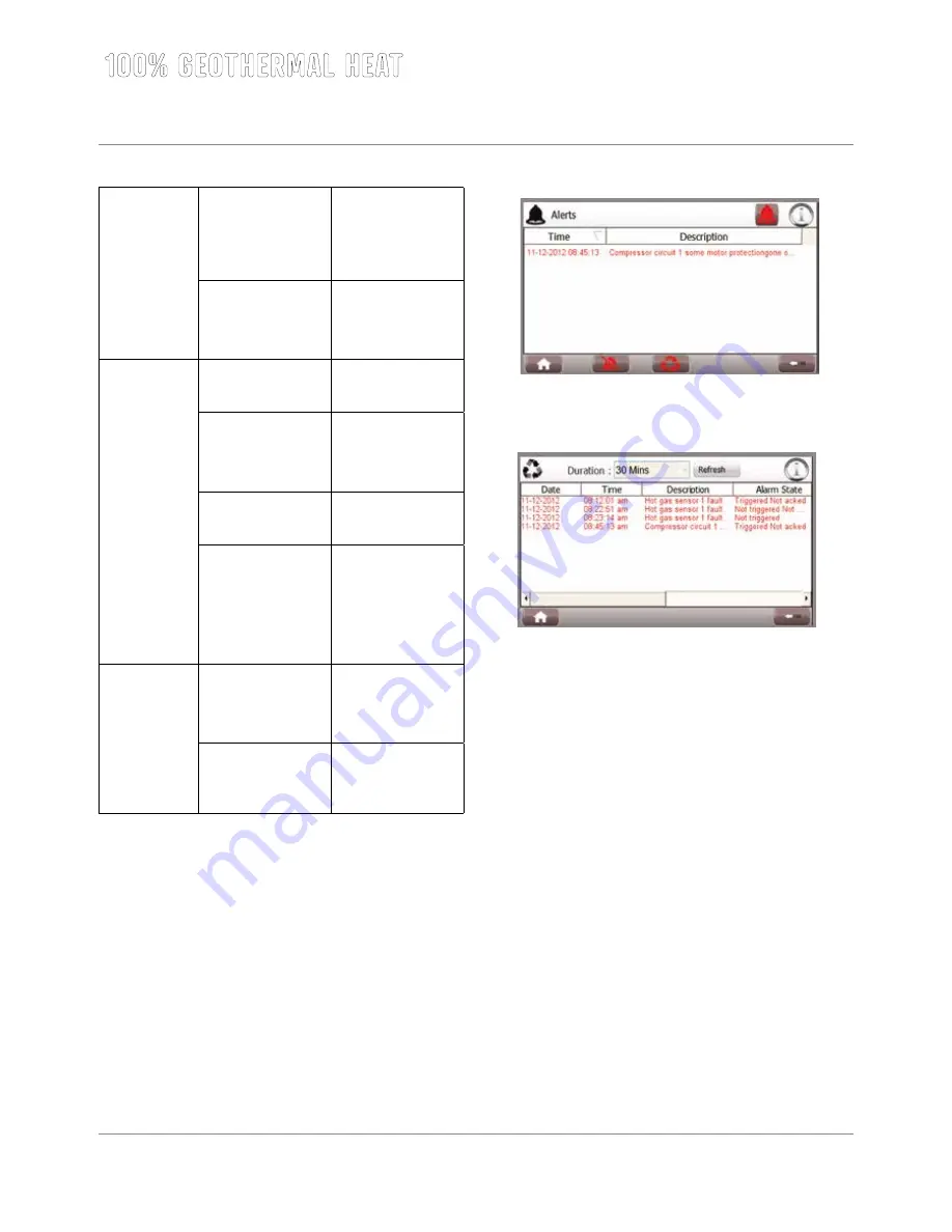
There are two ways to examine the alarms with ÄssäControl. 

• 

You can see the active alarms if you press the alarm bell on front 
page.  You  can  check  out  the  alarms  by  pressing  the  check  out 
alarms -button. You can go to alarm history from active alarms page 
by pressing the button at the bottom of the page. 


• 

You can see earlier alarms by pressing the alarm history -button at 
the menu functions.

The software automatically stores the newest 100 fault messages. This 
menu allows resetting the fault log data stored. Possible alarms in Vmi 
ground source heat pump:

• 

Compressor  1  circuit  1  some  motor  protection  gone  off.  Check 

motor protection F1, F2 or F3.

• 

Compressor 1 internal heat protection gone off. Wait 45 min.

• 

Low pressure pressostat of circuit 1 functioned. Accept presostat.

• 

High pressure pressostat of circuit 1 functioned. Accept presostat.

• 

Incorrect phase order. Change feed phase order.

• 

Temperature did not rise in pre set time. Resistance enabled.

• 

Not started information from compressor 1.

• 

Disturbance alarm from soft starter AK1 or AK4.

• 

Outside temperatur sensor fault.

• 

Hot gas sensor 1 fault.

• 

Low boiler sensor fault.

• 

Top boiler sensor fault.

• 

Heating circuit 1 sensor fault.

• 

Heating circuit 2 sensor fault.

• 

Heating circuit 3 sensor fault.

• 

Hot water temperature sensor fault

• 

Room temperature sensor fault.

• 

Alarm of liquid circuit

• 

External alarm

• 

Resistor functioned in full power system

Summary of Contents for VMI 6-17

Page 1: ...L MP SS Vmi 6 17 L MP SS 3 2016 INSTRUCTIONS FOR USE INSTALLATION AND MAINTENANCE...

Page 2: ...L mp ss for many decades to come Please familiar ize yourself with these instructions for use and maintenance Keep the instructions for future use and reference should problems occur These instructio...

Page 3: ...rt 15 4 1 2 Ground source heat pump installation area 15 4 1 3 Removing the packaging 15 4 1 4 Space requirements 16 4 2 HVAC installation 16 4 2 1 Heat collection circuit and fill group installation...

Page 4: ...storage tank Heat collection circuit Heating water Domestic water Compressor Evaporator Superheater Condenser Press this button for additional information on the touch screen data The type plate of th...

Page 5: ...5 Expansion valve 6a Upper storage tank 6b Lower storage tank 7a Upper storage tank domestic water coil 7b Lower storage tank domestic water coil 2 1 2 Compressor unit From the evaporator refrigerant...

Page 6: ...oil into two parts allows heating of the domestic water circulation only using the upper storage tank coil so that blending of the storage tank temperature stratifications is avoided 2 2 ss Cooling co...

Page 7: ...the bottom left corner to return to the home screen Use the arrow button in the bottom right corner to return to previous screen For instructions screen press the i button in the top right corner In...

Page 8: ...s which can be accessed by pressing the button at the bottom centre of the screen In case of compen sation value 7 the adjustment is seven times faster than in case of value 1 Large compensation value...

Page 9: ...nd date or time is in the future If the end date is set into the past the mode Home is activated and the mode Away cannot be activated 3 4 5 Measurements This shortcut allows accessing the Measurement...

Page 10: ...ustment curves are set higher than the storage tank temperature Factory settings for the storage tank bottom section are 40 C min and 45 C max Factory settings for the storage tank top section are 50...

Page 11: ...ther modifications in adjustment curve set values When using radiator heating temperature change is quicker Conditions in Finland pumps and 60 C bottom section 85 C top section in case of part power g...

Page 12: ...it value between 0 90 C factory set ting 55 C 3 5 3 Other set values The menu Other set values allows circuit specific programming of maxi mum and minimum heat distribution circuit supply water values...

Page 13: ...erature is not achieved by the com pressor during the dedicated period from 0 to 24 hours factory setting 12 hours The setting is applicable in full power systems only 3 5 3 5 Bivalent settings in biv...

Page 14: ...a Use the screen numbering in the bottom bar for navigating between the Measurements screens Measurements screen values describe heat pump operation under various conditions and the values shown canno...

Page 15: ...ource heat pump s accessory package includes adjustable feet to be screwed into the unit bottom see picture After that remove the wooden platform elements and their fixation screws 4 pc To remove the...

Page 16: ...1 with a frost resistance of 16 C reinforced hose 1 2 pc length approx 3 m connector 3 4 female thread for reinforced hose connector 1 female thread for reinforced hose WORK STAGES Please check that...

Page 17: ...11 J hdytys paluu Cooling return 1 12 Aurinkoyhde meno Solar connection flow 13 Aurinkoyhde paluu Solar connection return 14 Kv kierto Hot water circulation Varaajan t yt n yhteydess varaajassa oleva...

Page 18: ...unit The mixing valve is fitted to the hot water pipe in order to prevent burns The overflow pipe is joined to the floor drain as instructed or to an overflow funnel if the distance to the floor drai...

Page 19: ...ormal outdoor temperature Device Terminal block No Conductor type Outdoor sensor NTC X1 10 ja X1 2 2 X 0 7 mm2 4 3 2 Room sensor optional In order for the room sensor to detect average indoor temperat...

Page 20: ...from starting water in the storage tank has been heated by the electric heating element for at least 6 hours Possible problems during startup Problem Cause Solution Fuses always blow when the compres...

Page 21: ...condition of the fuses in the master switchboard Incorrect power supply phase sequence Contact an electrician The compressor does not start and the display reads Incor rect phase sequence or Motor pro...

Page 22: ...t of heat is needed for example the outdoor tem perature is very low or the structure is drying during the first year s use of the building No action required Lack of refrigerant Can be detected from...

Page 23: ...e alarm circuit 1 3 Brine pump 1 Run indicator 12 Compressor 1 Run indicator 4 13 5 14 Soft Starter 6 15 External Alarm 7 Compressor 1 internal alarm 16 8 17 Flow Sensor 9 Phase failure detector 18 Di...

Page 24: ...t water sensor 4 Boiler foot part temperature sensor 9 Inside temperature sensor 5 Outside temperatur sensor 10 Brine temperature sensor Analog outputs This screen allows checking analog output status...

Page 25: ...ivative time the more the regulator position changes upon each adjust ment Consider that increase in derivative time may result in increased regulator fluctuation Voltage 0 10 V Position valve control...

Page 26: ...method to use 5 4 9 Temperature gauges This screen allows choosing the temperature gauges used By default the outdoor temperature gauge is present Indoor temperature gauge is optional 5 4 10 External...

Page 27: ...percentage indicated in the valve setting point L mp ss unit Factroy setting Vmi 6 11 30 Vmi 14 17 40 5 4 13 Boiler maximum limits Maximum boiler limits are set on this page 5 4 14 Cooling Selectable...

Page 28: ...ions over 10 of the nominal voltage lightning fire or other respective event Transport damages are not covered by the warranty Also the warranty does not cover situations WARRANTY CONDITIONS caused by...

Page 29: ...rve 3 Constant curve 3 Constant curve 3 Factory setting of superheat circuit 30 35 35 35 40 40 40 Sound power level 1 dB 38 41 36 41 38 43 42 OPERATION LIMITS Temperature limits brine water C 10 60 15...

Page 30: ...48 0 59 0 70 0 68 0 89 0 83 1 00 Maximum external pressuredrop kPa 66 65 96 100 84 91 77 HEAT DISTRIBUTION CIRCUIT Energy class of HC pump A inverter A inverter A inverter A inverter A inverter A inv...

Page 31: ...XL 2015 811 2013 A A A B C D E F G A A A B C D E F G Vmi 6 38 dB 00 dB 8 kW 8 kW 8 kW...

Page 32: ...A A A A A A A A B C D E F G A A A A B C D E F G XL 2015 811 2013 XL X Vmi 6...

Page 33: ...Colder 4786 kWh a Warmer 2695 kWh a Annual electricity consumption for water heating under colder and warmer climate conditions Colder 1251 kWh a Warmer 1251 kWh a Energy efficiency for space heating...

Page 34: ...2 C Operation limit temperatures Heating Average TOL 10 C Warmer TOL 22 C Colder TOL 2 C Seasonal electricity consumption Heating Average QHE A 4116 kWh a Warmer QHE W 4786 kWh a Colder QHE C 2695 kW...

Page 35: ...XL 2015 811 2013 A A A B C D E F G A A A B C D E F G Vmi 9 41 dB 00 dB 10 kW 10 kW 10 kW...

Page 36: ...A A A A A A A A B C D E F G A A A A B C D E F G XL 2015 811 2013 XL X Vmi 9...

Page 37: ...s Colder 6181 kWh a Warmer 3418 kWh a Annual electricity consumption for water heating under colder and warmer climate conditions Colder 1308 kWh a Warmer 1308 kWh a Energy efficiency for space heatin...

Page 38: ...alent 2 C Operation limit temperatures Heating Average TOL 10 C Warmer TOL 22 C Colder TOL 2 C Seasonal electricity consumption Heating Average QHE A 5296 kWh a Warmer QHE W 6181 kWh a Colder QHE C 34...

Page 39: ...XL 2015 811 2013 A A A B C D E F G A A A B C D E F G Vmi 11 36 dB 00 dB 11 kW 11 kW 11 kW...

Page 40: ...A A A A A A A A B C D E F G A A A A B C D E F G XL 2015 811 2013 XL X Vmi 11...

Page 41: ...ns Colder 6899 kWh a Warmer 3837 kWh a Annual electricity consumption for water heating under colder and warmer climate conditions Colder 1214 kWh a Warmer 1214 kWh a Energy efficiency for space heati...

Page 42: ...Tbivalent 2 C Operation limit temperatures Heating Average TOL 10 C Warmer TOL 22 C Colder TOL 2 C Seasonal electricity consumption Heating Average QHE A 5296 kWh a Warmer QHE W 6899 kWh a Colder QHE...

Page 43: ...XL 2015 811 2013 A A A B C D E F G A A A B C D E F G Vmi 11 1x230V 41 dB 00 dB 11 kW 11 kW 11 kW...

Page 44: ...A A A A A A A A B C D E F G A A A A B C D E F G XL 2015 811 2013 XL X Vmi 11 1x230V...

Page 45: ...tions Colder 7106 kWh a Warmer 3908 kWh a Annual electricity consumption for water heating under colder and warmer climate conditions Colder 1267 kWh a Warmer 1267 kWh a Energy efficiency for space he...

Page 46: ...Tbivalent 2 C Operation limit temperatures Heating Average TOL 10 C Warmer TOL 22 C Colder TOL 2 C Seasonal electricity consumption Heating Average QHE A 6082 kWh a Warmer QHE W 7106 kWh a Colder QHE...

Page 47: ...XL 2015 811 2013 A A A B C D E F G A A A B C D E F G Vmi 14 38 dB 00 dB 14 kW 14 kW 14 kW...

Page 48: ...A A A A A A A A B C D E F G A A A A B C D E F G XL 2015 811 2013 XL X Vmi 14...

Page 49: ...ns Colder 8645 kWh a Warmer 4819 kWh a Annual electricity consumption for water heating under colder and warmer climate conditions Colder 1210 kWh a Warmer 1210 kWh a Energy efficiency for space heati...

Page 50: ...Tbivalent 2 C Operation limit temperatures Heating Average TOL 10 C Warmer TOL 22 C Colder TOL 2 C Seasonal electricity consumption Heating Average QHE A 7443 kWh a Warmer QHE W 8645 kWh a Colder QHE...

Page 51: ...XL 2015 811 2013 A A A B C D E F G A A A B C D E F G Vmi 14 1x230V 43 dB 00 dB 14 kW 14 kW 14 kW...

Page 52: ...A A A A A A A A B C D E F G A A A A B C D E F G XL 2015 811 2013 XL X Vmi 14 1x230V...

Page 53: ...tions Colder 9032 kWh a Warmer 5014 kWh a Annual electricity consumption for water heating under colder and warmer climate conditions Colder 1334 kWh a Warmer 1334 kWh a Energy efficiency for space he...

Page 54: ...Tbivalent 2 C Operation limit temperatures Heating Average TOL 10 C Warmer TOL 22 C Colder TOL 2 C Seasonal electricity consumption Heating Average QHE A 7627 kWh a Warmer QHE W 9032 kWh a Colder QHE...

Page 55: ...XL 2015 811 2013 A A A B C D E F G A A A B C D E F G Vmi 17 42 dB 00 dB 17 kW 17 kW 17 kW...

Page 56: ...A A A A A A A A B C D E F G A A A A B C D E F G XL 2015 811 2013 XL X Vmi 17...

Page 57: ...s Colder 10145 kWh a Warmer 5634 kWh a Annual electricity consumption for water heating under colder and warmer climate conditions Colder 1272 kWh a Warmer 1272 kWh a Energy efficiency for space heati...

Page 58: ...Tbivalent 2 C Operation limit temperatures Heating Average TOL 10 C Warmer TOL 22 C Colder TOL 2 C Seasonal electricity consumption Heating Average QHE A 8716 kWh a Warmer QHE W 10145 kWh a Colder QHE...

Page 59: ...e front part mas ter fuses 25 A Hysteresis 21 Current 25 28 Delay 1s The relay requires external voltage 24 240 V AC External supply is connected to terminals A1 and A2 Terminals 15 and 16 are connect...

Page 60: ......

Page 61: ......

Page 62: ......

Page 63: ......

Page 64: ......

Page 65: ......

Page 66: ......

Page 67: ......

Page 68: ......

Page 69: ......

Page 70: ......

Page 71: ......

Page 72: ......

Page 73: ......

Page 74: ......

Page 75: ......

Page 76: ......

Page 77: ......

Page 78: ......

Page 79: ......

Page 80: ......

Page 81: ......

Page 82: ......

Page 83: ......

Page 84: ......

Page 85: ......

Page 86: ......

Page 87: ......

Page 88: ......

Page 89: ......

Page 90: ......

Page 91: ......

Page 92: ......

Page 93: ...L mp ss is a trademark of Suomen L mp pumpputekniikka Oy We reserve the right to make changes Suomen L mp pumpputekniikka Oy Unikontie 2 62100 Lapua www lampoassa com R...

Reviews: