24
100% GEOTHERMAL HEAT
24
MAINTENANCE MANUAL
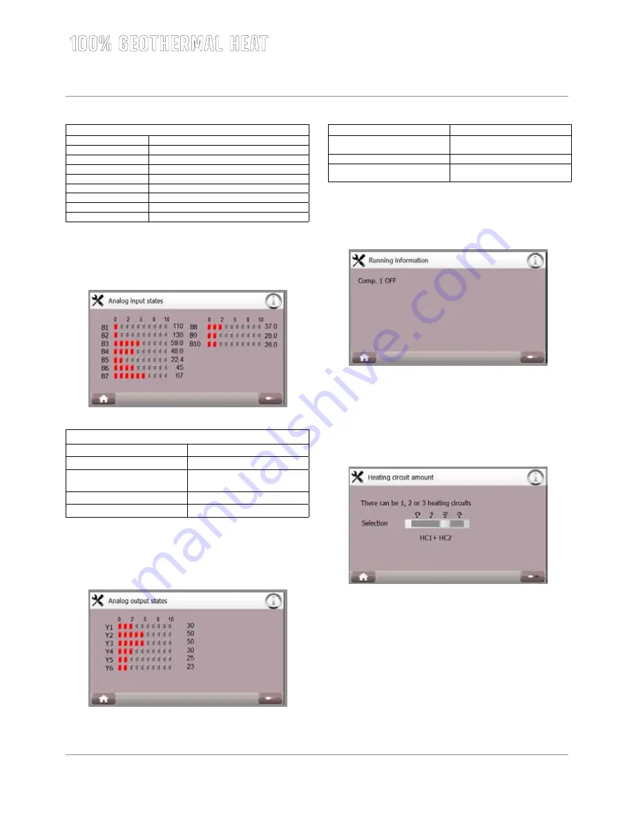
Use the button in the bottom left corner to return to the home screen. Use the arrow button in the bottom right corner to return to previous screen.
For instructions screen, press the ‘i’ button in the top right corner. In case of operation faults, an alarm button is displayed on the top bar.
Digital Output (NO)
1 Brine circuit 1
10
2
11
3 Alarm signal
12 Immersion heater 4
4 Compressor 1
13 Immersion heater 1
5 Condenser pump 1
14 Heating circuit pump 1
6 Magnetic valve 1
15 Heating circuit pump 2
7 Immersion heater 2
16 Heating circuit pump 3
8 Immersion heater 3
17
9
18 Pressure equalizing valve (Only 1-phase devices)
Analog inputs
This screen allows checking analog input statuses.
Analog Input (B)
1 Hot gas sensor 1
6 Circuit 1 outgoing temperature sensor
2
7 Circuit 2 outgoing temperature sensor
3 Boiler top part temperature sensor
8 Circuit 3 outgoing temperature / Me
-
asurement of domestic hot water sensor
4 Boiler foot part temperature sensor
9 Inside temperature sensor
5 Outside temperatur sensor
10 Brine temperature sensor
Analog outputs
This screen allows checking analog output statuses.
Analog Output (Y)
1 Heating circuit 1 regulation motor
4 Heating circuit 3 regulation motor/
Adjusment of domestic hot water
2 Heating circuit 2 regulation motor
5 Speed regulation of brine pump
3 Analog immersion heater control
0-10V
6 Superheat valve regulation
5.4.3. Running information
This screen shows compressor’s current state.
5.4.4. Heat distribution circuit quantity
There may be from 1 to 3 heat distribution circuits, of which circuits 2 and
3 are optional. If three heat distribution circuits are in use, the domestic
water temperature limit function cannot be used at the same time.
5.4.5. Domestic hot water temperature limit
This screen allows activation of the domestic hot water temperature limit
and changing of the domestic hot water temperature sensor and the
related position valve connection location. The default setting is that the
temperature sensor is connected to analog input B8 and position valve to
analog output Y4.
Summary of Contents for VMI 6-17
Page 1: ...L MP SS Vmi 6 17 L MP SS 3 2016 INSTRUCTIONS FOR USE INSTALLATION AND MAINTENANCE...
Page 31: ...XL 2015 811 2013 A A A B C D E F G A A A B C D E F G Vmi 6 38 dB 00 dB 8 kW 8 kW 8 kW...
Page 32: ...A A A A A A A A B C D E F G A A A A B C D E F G XL 2015 811 2013 XL X Vmi 6...
Page 35: ...XL 2015 811 2013 A A A B C D E F G A A A B C D E F G Vmi 9 41 dB 00 dB 10 kW 10 kW 10 kW...
Page 36: ...A A A A A A A A B C D E F G A A A A B C D E F G XL 2015 811 2013 XL X Vmi 9...
Page 39: ...XL 2015 811 2013 A A A B C D E F G A A A B C D E F G Vmi 11 36 dB 00 dB 11 kW 11 kW 11 kW...
Page 40: ...A A A A A A A A B C D E F G A A A A B C D E F G XL 2015 811 2013 XL X Vmi 11...
Page 44: ...A A A A A A A A B C D E F G A A A A B C D E F G XL 2015 811 2013 XL X Vmi 11 1x230V...
Page 47: ...XL 2015 811 2013 A A A B C D E F G A A A B C D E F G Vmi 14 38 dB 00 dB 14 kW 14 kW 14 kW...
Page 48: ...A A A A A A A A B C D E F G A A A A B C D E F G XL 2015 811 2013 XL X Vmi 14...
Page 52: ...A A A A A A A A B C D E F G A A A A B C D E F G XL 2015 811 2013 XL X Vmi 14 1x230V...
Page 55: ...XL 2015 811 2013 A A A B C D E F G A A A B C D E F G Vmi 17 42 dB 00 dB 17 kW 17 kW 17 kW...
Page 56: ...A A A A A A A A B C D E F G A A A A B C D E F G XL 2015 811 2013 XL X Vmi 17...
Page 60: ......
Page 61: ......
Page 62: ......
Page 63: ......
Page 64: ......
Page 65: ......
Page 66: ......
Page 67: ......
Page 68: ......
Page 69: ......
Page 70: ......
Page 71: ......
Page 72: ......
Page 73: ......
Page 74: ......
Page 75: ......
Page 76: ......
Page 77: ......
Page 78: ......
Page 79: ......
Page 80: ......
Page 81: ......
Page 82: ......
Page 83: ......
Page 84: ......
Page 85: ......
Page 86: ......
Page 87: ......
Page 88: ......
Page 89: ......
Page 90: ......
Page 91: ......
Page 92: ......


