25
25
MAINTENANCE MANUAL
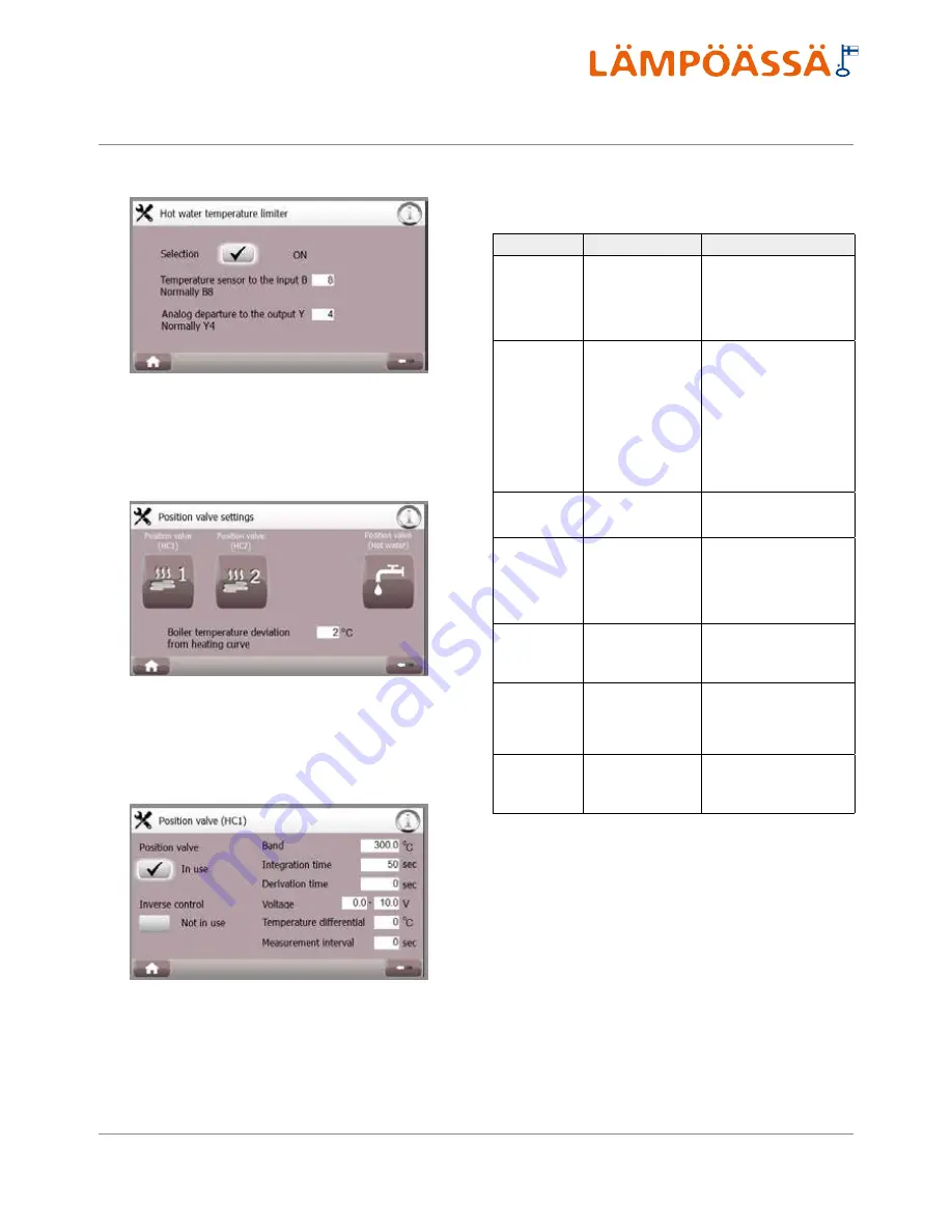
Use the button in the bottom left corner to return to the home screen. Use the arrow button in the bottom right corner to return to previous screen.
For instructions screen, press the ‘i’ button in the top right corner. In case of operation faults, an alarm button is displayed on the top bar.
The following settings are possible for all circuits:
Setting
Description
Example
Reverse control
(ON/OFF)
Reversing of position
valve adjustment
direction
In the OFF position, if voltage
is 0 V, the regulator is in its
extreme right position. In the
ON position, if voltage is 0 V,
the regulator is in its extreme
left position.
Adjustment range
(10...600°C)
The divergence from
target temperature in
which case the position
valve is adjusted from
one extreme position
to another. Factory set
-
ting: 300 °C.*
If the adjustment range is 140
°C and the target tempera
-
ture differs from the current
temperature by 14 °C, the
valve is adjusted to 10% of the
maximum. If the tempera
-
ture changes too quickly, the
adjustment range is increased.
If the temperature changes too
slowly, the adjustment range is
decreased.
Integration time
(5...300 s)
Temperature divergence
correction interval(s).
Factory setting: 50 s.**
If integration time is 10 s, the
valve position is changed once
in every 10 s, if required.
Derivative time
(0...10 s)
Temperature divergence
reaction time. Factory
setting: 0.
The longer the derivative time,
the more the regulator position
changes upon each adjust
-
ment. Consider that increase
in derivative time may result in
increased regulator fluctuation.
Voltage
(0...10 V)
Position valve control
voltage min and max
values. Factory setting:
0.0-10.0 VAC.
This setting depends on the
regulator used.
Temperature
divergence
(0...10 °C)
Allowed divergence
from target tempera
-
ture. Factory setting:
0
°C
.
At value 5 °C, the regulator
position is changed only after
the difference between the
actual temperature and target
temperature exceeds 5 °C.
Frequency of
measurements
(0...30 s)
How often is the
current temperature
checked. Factory set
-
ting: 0.
At value 15 s, the current
temperature is checked once
in every 15 s. At value 0 the
checking is continuous.
* Domestic water limit 30 °C
** Domestic water limit 40 s.
5.4.7. Part-power / Full power
The maintenance menu allows switching between full power (default
setting) and part-power, in which case the equipment allows activation
of the electric heating element or some other source of additional heat
simultaneously with the compressor.
5.4.6. Positioning valve control
This screen allows determining the settings of position valves associated
with heat distribution circuits and domestic hot water temperature limit.
Each adjustable circuit has two setting screens.
If the temperature at storage tank bottom part is lower than that of the heat
distribution circuit, the storage tank temperature is automatically increased
so as to meet the heat distribution circuit temperature with additional diver
-
gence value. Adjustment range 0...10 °C, factory setting 2 °C.
Summary of Contents for VMI 6-17
Page 1: ...L MP SS Vmi 6 17 L MP SS 3 2016 INSTRUCTIONS FOR USE INSTALLATION AND MAINTENANCE...
Page 31: ...XL 2015 811 2013 A A A B C D E F G A A A B C D E F G Vmi 6 38 dB 00 dB 8 kW 8 kW 8 kW...
Page 32: ...A A A A A A A A B C D E F G A A A A B C D E F G XL 2015 811 2013 XL X Vmi 6...
Page 35: ...XL 2015 811 2013 A A A B C D E F G A A A B C D E F G Vmi 9 41 dB 00 dB 10 kW 10 kW 10 kW...
Page 36: ...A A A A A A A A B C D E F G A A A A B C D E F G XL 2015 811 2013 XL X Vmi 9...
Page 39: ...XL 2015 811 2013 A A A B C D E F G A A A B C D E F G Vmi 11 36 dB 00 dB 11 kW 11 kW 11 kW...
Page 40: ...A A A A A A A A B C D E F G A A A A B C D E F G XL 2015 811 2013 XL X Vmi 11...
Page 44: ...A A A A A A A A B C D E F G A A A A B C D E F G XL 2015 811 2013 XL X Vmi 11 1x230V...
Page 47: ...XL 2015 811 2013 A A A B C D E F G A A A B C D E F G Vmi 14 38 dB 00 dB 14 kW 14 kW 14 kW...
Page 48: ...A A A A A A A A B C D E F G A A A A B C D E F G XL 2015 811 2013 XL X Vmi 14...
Page 52: ...A A A A A A A A B C D E F G A A A A B C D E F G XL 2015 811 2013 XL X Vmi 14 1x230V...
Page 55: ...XL 2015 811 2013 A A A B C D E F G A A A B C D E F G Vmi 17 42 dB 00 dB 17 kW 17 kW 17 kW...
Page 56: ...A A A A A A A A B C D E F G A A A A B C D E F G XL 2015 811 2013 XL X Vmi 17...
Page 60: ......
Page 61: ......
Page 62: ......
Page 63: ......
Page 64: ......
Page 65: ......
Page 66: ......
Page 67: ......
Page 68: ......
Page 69: ......
Page 70: ......
Page 71: ......
Page 72: ......
Page 73: ......
Page 74: ......
Page 75: ......
Page 76: ......
Page 77: ......
Page 78: ......
Page 79: ......
Page 80: ......
Page 81: ......
Page 82: ......
Page 83: ......
Page 84: ......
Page 85: ......
Page 86: ......
Page 87: ......
Page 88: ......
Page 89: ......
Page 90: ......
Page 91: ......
Page 92: ......


