9
USER MANUAL
Use the button in the bottom left corner to return to the home screen. Use the arrow button in the bottom right corner to return to previous screen.
For instructions screen, press the ‘i’ button in the top right corner. In case of operation faults, an alarm button is displayed on the top bar.
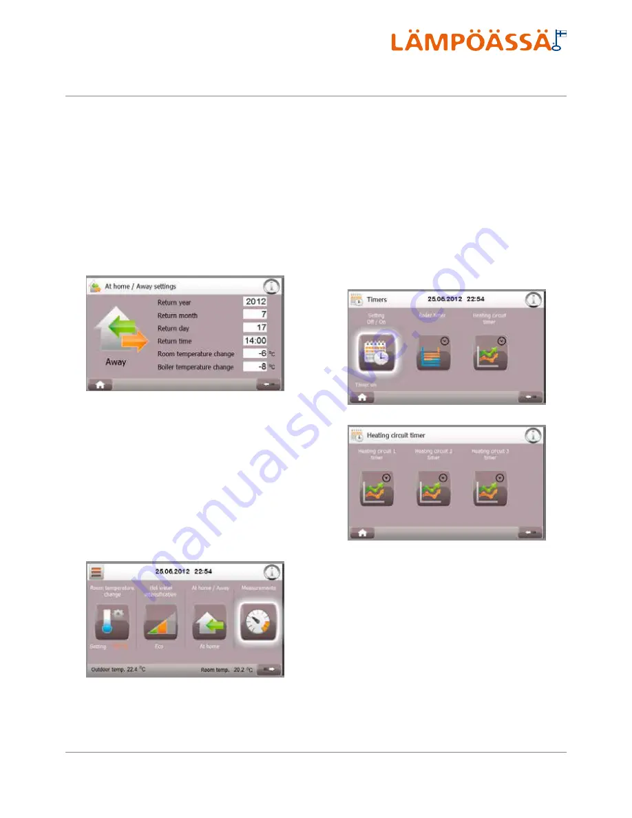
Set the desired heat distribution circuit temperature adjustment under
Room temperature adjustment; values between -10...+10 °C are possi
-
ble. Set the desired storage tank temperature adjustment value under
Storage tank temperature adjustment. This setting influences domestic
water temperature. Values between -10...+10 °C are possible. If any of
these temperatures is not to be changed, keep 0 °C as its value. When
leaving for a holiday trip, for example, both of the values might be low
-
ered by approx. 5 degrees by setting -5 °C as the room/storage tempera
-
ture adjustment value.
The function can be activated only if the end date or time is in the future.
If the end date is set into the past, the mode Home is activated and the
mode Away cannot be activated.
3.4.5. Measurements
This shortcut allows accessing the
Measurements
menu, which will be
discussed in more detail in the Section on menu functions.
3.4.6. Timer functions
Timer functions can be utilised, for example, in secondary residences or
to benefit from off-peak electricity rates, in which case weekday-specific
modification of temperature levels is advantageous. The values once set
are saved in the memory and can be modified as necessary.
The timer function can be activated or removed from use through the
Timer functions
shortcut. On the
Timer functions
screen, the timing
target (storage tank or heat distribution circuit) is selected and the timer
function activated/deactivated.
On the following screens, the target weekdays for timed temperature
changes are selected. On the screens, the temperature change beginning
and end times (in full hours) can be set in weekday-specific manner, as
well as the change in degrees. Temperature change values between
-10...+10 °C are possible.
Summary of Contents for VMI 6-17
Page 1: ...L MP SS Vmi 6 17 L MP SS 3 2016 INSTRUCTIONS FOR USE INSTALLATION AND MAINTENANCE...
Page 31: ...XL 2015 811 2013 A A A B C D E F G A A A B C D E F G Vmi 6 38 dB 00 dB 8 kW 8 kW 8 kW...
Page 32: ...A A A A A A A A B C D E F G A A A A B C D E F G XL 2015 811 2013 XL X Vmi 6...
Page 35: ...XL 2015 811 2013 A A A B C D E F G A A A B C D E F G Vmi 9 41 dB 00 dB 10 kW 10 kW 10 kW...
Page 36: ...A A A A A A A A B C D E F G A A A A B C D E F G XL 2015 811 2013 XL X Vmi 9...
Page 39: ...XL 2015 811 2013 A A A B C D E F G A A A B C D E F G Vmi 11 36 dB 00 dB 11 kW 11 kW 11 kW...
Page 40: ...A A A A A A A A B C D E F G A A A A B C D E F G XL 2015 811 2013 XL X Vmi 11...
Page 44: ...A A A A A A A A B C D E F G A A A A B C D E F G XL 2015 811 2013 XL X Vmi 11 1x230V...
Page 47: ...XL 2015 811 2013 A A A B C D E F G A A A B C D E F G Vmi 14 38 dB 00 dB 14 kW 14 kW 14 kW...
Page 48: ...A A A A A A A A B C D E F G A A A A B C D E F G XL 2015 811 2013 XL X Vmi 14...
Page 52: ...A A A A A A A A B C D E F G A A A A B C D E F G XL 2015 811 2013 XL X Vmi 14 1x230V...
Page 55: ...XL 2015 811 2013 A A A B C D E F G A A A B C D E F G Vmi 17 42 dB 00 dB 17 kW 17 kW 17 kW...
Page 56: ...A A A A A A A A B C D E F G A A A A B C D E F G XL 2015 811 2013 XL X Vmi 17...
Page 60: ......
Page 61: ......
Page 62: ......
Page 63: ......
Page 64: ......
Page 65: ......
Page 66: ......
Page 67: ......
Page 68: ......
Page 69: ......
Page 70: ......
Page 71: ......
Page 72: ......
Page 73: ......
Page 74: ......
Page 75: ......
Page 76: ......
Page 77: ......
Page 78: ......
Page 79: ......
Page 80: ......
Page 81: ......
Page 82: ......
Page 83: ......
Page 84: ......
Page 85: ......
Page 86: ......
Page 87: ......
Page 88: ......
Page 89: ......
Page 90: ......
Page 91: ......
Page 92: ......


