164
8
Options
8
Options
8.1
Firing-Rate Controller Module LCM100
The LCM100 adds the function of a firing rate controller to the BurnerTronic. Additional com-
ponents of the module are:
–
An integrated power supply for external 24 V consumers
(sensors, additional BurnerTronic expansion modules)
–
A LSB interface for connecting additional LSB devices
–
A 4 ... 20 mA monitor output, for internal firing rate
–
Digital pulse counter inputs for calculating fuel consumption
–
A Pt100/1000 input for measuring flue gas temperature
–
Socket for connection of BT300 service software
The firing rate controller offers the option of controlling temperature (Pt100 or Pt1000) or
steam pressure (4 ... 20 mA pressure sensor). The LCM100 also offers the option of a setpoint
shift depending on outside temperature (control by atmospheric condition). If the control by at-
mospheric condition function is not in use, 2 programmed setpoints can be controlled using a
digital 24 V input.
LCM100 insulates the LSB from BT300’s mains potential.
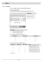
Set the configuration of the connected flame-sensors with DIP switches.
The burner firing rate controller function can be disabled, if required. In this case the regular
firing rate input can be controlled either by a 4 ... 20 mA, 0 ... 10 V or a three-point step (TPS),
input.
NOTICE
For a precise adjustment consider parameters 40 - 60. For more information regarding these
parameters refer to document ’Commissioning Supplement Parameter List’ (DLT1204).
NOTICE
When using a manual regular firing rate input the firing rate controller must be activated.
P 40 = 1 or 2 (up to version 1.3.0.0)
P 40 = 3 (version 1.4.0.0 and higher).
8.1.1
Range Limits
You must set limit values in the parameters, switching the burner on and off. After a burner
shut-down while actual temperature has not reached the switch-on threshold yet, a display will
inform you that firing rate controller is refusing a start-up.
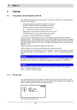
Fig. 8-1 Message Start-up denied
Summary of Contents for BT300 BurnerTronic
Page 2: ......
Page 25: ...24 3 Product Description Fig 3 9 Temperature derating BT300 for operation 2000 m NHN...
Page 49: ...48 4 Design and Functions Fig 4 20 Oil with pilot burner BT300...
Page 50: ...49 4 Design and Functions Fig 4 21 Oil without pilot burner BT300...
Page 51: ...50 4 Design and Functions Fig 4 22 Gas with pilot burner and leakage test BT300...
Page 52: ...51 4 Design and Functions Fig 4 23 Gas without pilot burner and leakage test BT300...
Page 53: ...52 4 Design and Functions Fig 4 24 Oil without pilot burner BT335...
Page 54: ...53 4 Design and Functions Fig 4 25 Gas without pilot burner and leakage test BT335...
Page 59: ...58 4 Design and Functions Fig 4 28 Leakage test process diagram...
Page 98: ...97 6 Operating Control and Displays...
Page 99: ...98 6 Operating Control and Displays...
Page 103: ...102 6 Operating Control and Displays...
Page 105: ...104 6 Operating Control and Displays...
Page 106: ...105 6 Operating Control and Displays...
Page 107: ...106 6 Operating Control and Displays...
Page 109: ...108 6 Operating Control and Displays...
Page 126: ...125 6 Operating Control and Displays 6 3 4 2 Curve Table Fig 6 37 Curve table window...
Page 246: ...242 10 EU Declaration of Conformity 10 EU Declaration of Conformity...
Page 247: ...243 10 EU Declaration of Conformity...

