241
8
Options
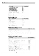
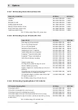
Tab. 8-26 CO/O
2
operating status for FMS/ETAMATIC and BT300
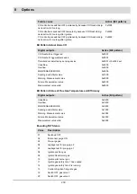
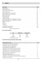
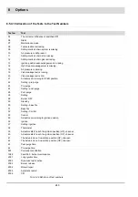
8.5.4.17 State Information
The subsequent table contains information, that describes the actual status of the burner con-
trol systems that will be transmitted via Bus. This table is applicable to:
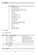
O
2
Trim is in the mode O
2
Setting.
68
O
2
Setpoint curve is invalid during operation
69
O
2
Optimisation curve is invalid during operation.
70
The time after a curve set change until activation of the O
2
trim is running.
71
O
2
Trim is deactivated by P142. Switching the O
2
trim ON an OFF in operation is possible.
72
Unknown CO/O
2
operating mode.
73
Invalid O
2
operating mode
74
O
2
Operating mode SWITCHING FROM O
2
TRIM TO CO CONTROL is running (BT300 v3.1 and higher).
75
O
2
Operating mode SWITCHING FROM CO CONTROL TO O
2
TRIM is running (BT300 v3.1 and higher).
76
SiCarboSen: CO control is inactive.
77
CO/O
2
Operating Condition
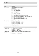
Value
Modbus:
Register 8257
PROFIBUS:
Register 8257
Modbus/TCP:
Output byte 14,15
Name
Description
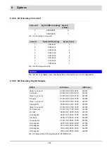
State information 1
The hint bits can be used in OR operations:
Hints of BT300:
0x0001 : 250.000 Burner starts
0x0002 : Maintenance mode is active
0x0004 : Fuel selection is missing
0x0008 : Safety interlock chain system is missing
0x0010 : Air pressure is still pending
0x0020 : Safety interlock chain oil is missing
0x0040 : Safety interlock chain gas is missing
0x0080 : Ignition position acknowledgement is missing
0x0100 : High fire acknowledgement is missing
0x0200 : Air pressure is missing
0x0400 : Valve leakage check is running
0x0800 : Valve leakage check is OK
0x1000 : Actuators are running to open position
0x2000 : Actuator does not reach ignition position (HP) channel-
0x4000 : Actuator does not reach ignition position (UP) channel-
0x8000 : Actuator is not in aeration position (HP) channel-
Summary of Contents for BT300 BurnerTronic
Page 2: ......
Page 25: ...24 3 Product Description Fig 3 9 Temperature derating BT300 for operation 2000 m NHN...
Page 49: ...48 4 Design and Functions Fig 4 20 Oil with pilot burner BT300...
Page 50: ...49 4 Design and Functions Fig 4 21 Oil without pilot burner BT300...
Page 51: ...50 4 Design and Functions Fig 4 22 Gas with pilot burner and leakage test BT300...
Page 52: ...51 4 Design and Functions Fig 4 23 Gas without pilot burner and leakage test BT300...
Page 53: ...52 4 Design and Functions Fig 4 24 Oil without pilot burner BT335...
Page 54: ...53 4 Design and Functions Fig 4 25 Gas without pilot burner and leakage test BT335...
Page 59: ...58 4 Design and Functions Fig 4 28 Leakage test process diagram...
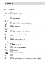
Page 98: ...97 6 Operating Control and Displays...
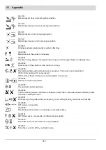
Page 99: ...98 6 Operating Control and Displays...
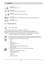
Page 103: ...102 6 Operating Control and Displays...
Page 105: ...104 6 Operating Control and Displays...
Page 106: ...105 6 Operating Control and Displays...
Page 107: ...106 6 Operating Control and Displays...
Page 109: ...108 6 Operating Control and Displays...
Page 126: ...125 6 Operating Control and Displays 6 3 4 2 Curve Table Fig 6 37 Curve table window...
Page 246: ...242 10 EU Declaration of Conformity 10 EU Declaration of Conformity...
Page 247: ...243 10 EU Declaration of Conformity...


