34
4
Design and Functions
NOTICE
When running oil-solely burning applications, the function ’Oil pressure > min’ is aligned with
X05. When running oil/gas burning applications (BT340 in combination with DFM300), the
function ’Gas > min’ is aligned with X05.
Put in oil/gas applications, the pressure monitoring for ’Oil pressure > min.’ in the oil safety
interlock chain (SIC).
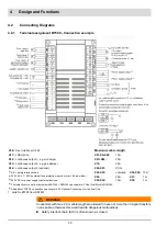
4.2.2
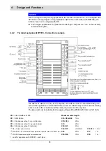
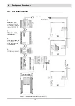
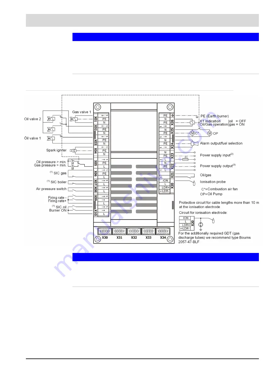
Terminal assignment BT335 - Connection example
NOTICE
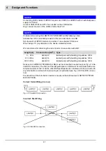
The effects of a failure of relay K1 at output 26 of the BT335 must be evaluated taking into
account the application in which the BT335 is used. A suitable relay must be used according
to the results of the evaluation and the safety requirements of the system.
The relay coil must be suitable for the supply voltage of the BT300 (230 VAC or 120 VAC).
X30
= User Interface UI 300
Maximum cable length:
X31
= LSB Option
X01–X06+X08:
10 m
X32
= Continuous output 1, e.g. air damper
X07+X09:
20 m
X33
= Continuous output 2, e.g. gas damper
X10:
20 m
X34
= Continuous output 3 (optional)
X20-X21:
20 m
(1)
SIC = Safety initerlock chain
X22-X23:
unlimited
X32-X34:
10 m
1
(2)
230 VAC 47 - 63 Hz external fuese protection required (max 10 A slow blow)
X24:
20 m
X31:
1 m
(3)
230 VAC for power supply to external devices
X25-X26:
10 m
X30:
1 m
1 valid for appliances with SN1801... and higher
Summary of Contents for BT300 BurnerTronic
Page 2: ......
Page 25: ...24 3 Product Description Fig 3 9 Temperature derating BT300 for operation 2000 m NHN...
Page 49: ...48 4 Design and Functions Fig 4 20 Oil with pilot burner BT300...
Page 50: ...49 4 Design and Functions Fig 4 21 Oil without pilot burner BT300...
Page 51: ...50 4 Design and Functions Fig 4 22 Gas with pilot burner and leakage test BT300...
Page 52: ...51 4 Design and Functions Fig 4 23 Gas without pilot burner and leakage test BT300...
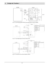
Page 53: ...52 4 Design and Functions Fig 4 24 Oil without pilot burner BT335...
Page 54: ...53 4 Design and Functions Fig 4 25 Gas without pilot burner and leakage test BT335...
Page 59: ...58 4 Design and Functions Fig 4 28 Leakage test process diagram...
Page 98: ...97 6 Operating Control and Displays...
Page 99: ...98 6 Operating Control and Displays...
Page 103: ...102 6 Operating Control and Displays...
Page 105: ...104 6 Operating Control and Displays...
Page 106: ...105 6 Operating Control and Displays...
Page 107: ...106 6 Operating Control and Displays...
Page 109: ...108 6 Operating Control and Displays...
Page 126: ...125 6 Operating Control and Displays 6 3 4 2 Curve Table Fig 6 37 Curve table window...
Page 246: ...242 10 EU Declaration of Conformity 10 EU Declaration of Conformity...
Page 247: ...243 10 EU Declaration of Conformity...


