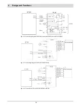
35
4
Design and Functions
WARNING!
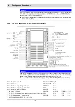
Conductors with max. 20 m cable length are allowed to have not more than 3 signal transfers
in one cable, otherwise this would lead to dangerous malfunctions.
Safety interlock chain is open but is detected as closed.
NOTICE
When running oil-solely burning applications, the function ’Oil pressure > min’ is aligned with
X05.When running oil/gas burning applications (BT340 in combination with DFM300), the
function ’Gas > min’ is aligned with X05
Put in oil/gas applications, the pressure monitoring for ’Oil pressure > min.’ in the oil safety
interlock chain (SIC).
BT335 is designed for basic 2-fuel burners.
The assignment of the terminals X01, X02, X03, X10, X21, X26 differs from the assignment of
the other BT300 types. The assignment of the connections mentioned below applies exclu-
sively to the described configuration.
If BT335 is configured like a BT320 or BT330, the terminal assignment of the corresponding
one applies.
•
X05
monitors the minimum fuel pressure in both gas and oil mode.
If there is no pressure switch for the minimum fuel pressure, this input must be bypassed
for the corresponding fuel.
•
BT335 does
not
support burners with pilot burner.
•
BT335 does
not
support 3-stage oil burners.
In oil mode, the burner can only be operated in modulating or 2-stage mode.
•
BT335 does
not
support CPI/POC applications.
•
An external fault release requires an LCM.
•
BT335 does
not
support applications with Siemens QRA2...,QRA4... and QRA10....
KLC1000 or KLC10 must be used for UV flame monitoring.
4.2.3
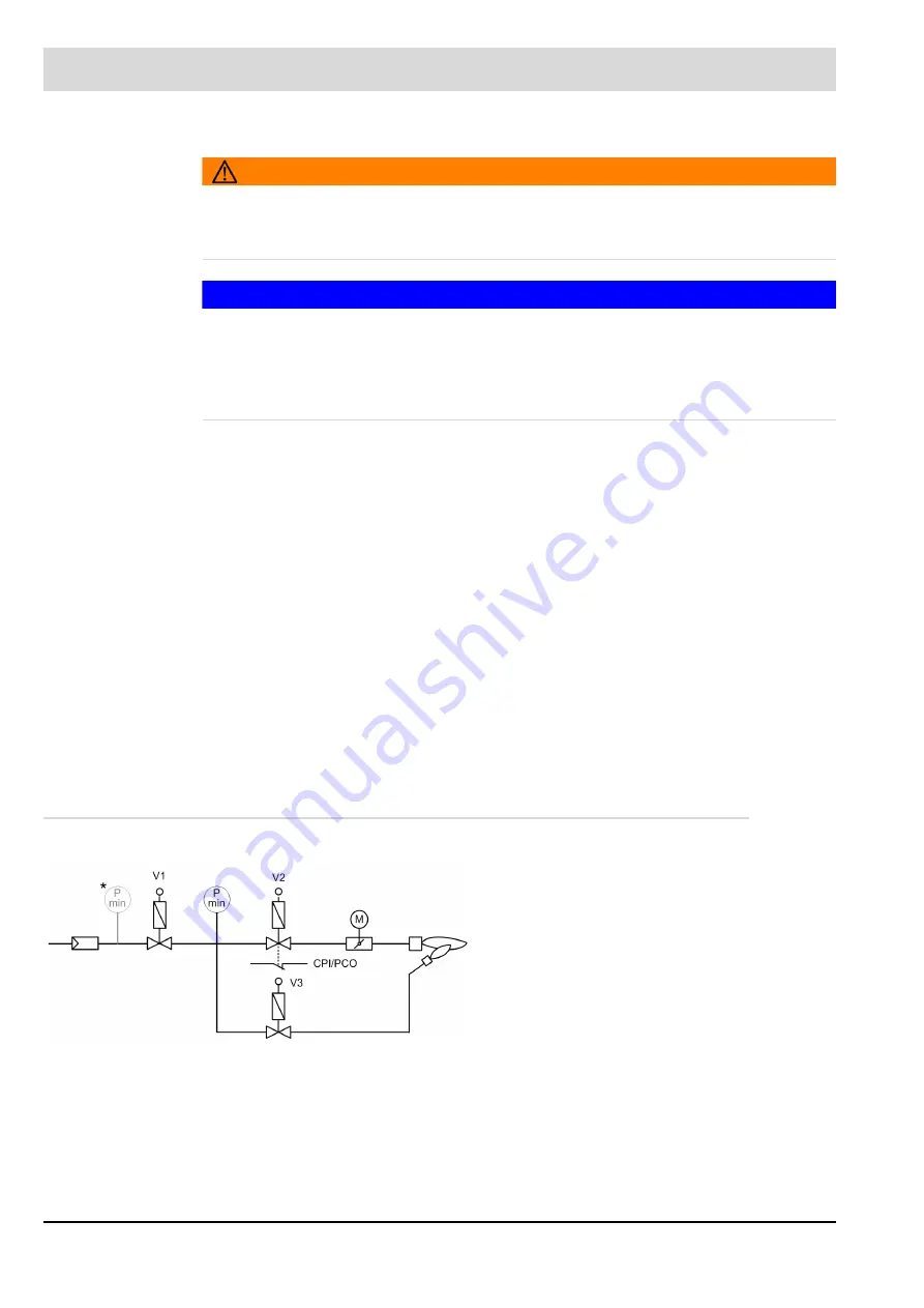
Optional Connections for the Fuel Line
Fig. 4-2 Fuel train - gas modulating
V1
Fuel valve (gas side)
V2
Fuel valve (burner side)
V3
Optional ignition valve
P
min
Gas pressure min sensor
M
Actuator gas damper
*
Alternative positioning of the pressure moni-
tor P
min
– if valve leakage check is not nec-
essary.
CPI/
POC
C
lose
P
osition
I
ndicator (UK/AU)
P
rove
O
f
C
losure (US)
ON switch at gas valve 2 which indicates
that the valve is closed (option)
Summary of Contents for BT300 BurnerTronic
Page 2: ......
Page 25: ...24 3 Product Description Fig 3 9 Temperature derating BT300 for operation 2000 m NHN...
Page 49: ...48 4 Design and Functions Fig 4 20 Oil with pilot burner BT300...
Page 50: ...49 4 Design and Functions Fig 4 21 Oil without pilot burner BT300...
Page 51: ...50 4 Design and Functions Fig 4 22 Gas with pilot burner and leakage test BT300...
Page 52: ...51 4 Design and Functions Fig 4 23 Gas without pilot burner and leakage test BT300...
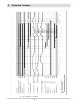
Page 53: ...52 4 Design and Functions Fig 4 24 Oil without pilot burner BT335...
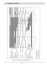
Page 54: ...53 4 Design and Functions Fig 4 25 Gas without pilot burner and leakage test BT335...
Page 59: ...58 4 Design and Functions Fig 4 28 Leakage test process diagram...
Page 98: ...97 6 Operating Control and Displays...
Page 99: ...98 6 Operating Control and Displays...
Page 103: ...102 6 Operating Control and Displays...
Page 105: ...104 6 Operating Control and Displays...
Page 106: ...105 6 Operating Control and Displays...
Page 107: ...106 6 Operating Control and Displays...
Page 109: ...108 6 Operating Control and Displays...
Page 126: ...125 6 Operating Control and Displays 6 3 4 2 Curve Table Fig 6 37 Curve table window...
Page 246: ...242 10 EU Declaration of Conformity 10 EU Declaration of Conformity...
Page 247: ...243 10 EU Declaration of Conformity...

