37
4
Design and Functions
Connection of the fuel valves see chapter
4.2.4
Optional Connections for the Flame Scanner
Electrical connections
NOTICE
Connecting the KLC.... and IRD... sensors to connector X20 incorrectly may damage the sen-
sors!
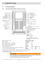
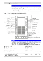
Fig. 4-5 Fuel train - oil modulating - oil 2-stage
P
min
Oil pressure min sensor
V1
Oil valve for modulated operation,
oil valve 1
st
stage at 2-stage operation
V2
Oil valve 2
nd
stage at 2-stage operation
V3
Optional ignition valve
M
Actuator for control valve oil/modulated opera-
tion
CPI/
POC
C
lose
P
osition
I
ndicator (UK/AU)
P
rove
O
f
C
losure (US)
ON switch at oil valve 1 which indicates that
the valve is closed (option)
CPI/POC
BT300
Burner ON
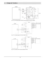
Fig. 4-6 Connecting diagram ionisation electrode
Fig. 4-7 Connecting diagram photo resistance e.g. Siemens
QRB... or Honeywell MZ770
Fig. 4-8 Connecting diagram of the sensor Honeywell IRD1020 Fig. 4-9 Connecting diagram of sensor Honeywell IRD1010,
KLC10, KLC20, KLC1000 or KLC2002
Colour code
BK
= black;
BN
= brown;
BU
= blue
Summary of Contents for BT300 BurnerTronic
Page 2: ......
Page 25: ...24 3 Product Description Fig 3 9 Temperature derating BT300 for operation 2000 m NHN...
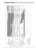
Page 49: ...48 4 Design and Functions Fig 4 20 Oil with pilot burner BT300...
Page 50: ...49 4 Design and Functions Fig 4 21 Oil without pilot burner BT300...
Page 51: ...50 4 Design and Functions Fig 4 22 Gas with pilot burner and leakage test BT300...
Page 52: ...51 4 Design and Functions Fig 4 23 Gas without pilot burner and leakage test BT300...
Page 53: ...52 4 Design and Functions Fig 4 24 Oil without pilot burner BT335...
Page 54: ...53 4 Design and Functions Fig 4 25 Gas without pilot burner and leakage test BT335...
Page 59: ...58 4 Design and Functions Fig 4 28 Leakage test process diagram...
Page 98: ...97 6 Operating Control and Displays...
Page 99: ...98 6 Operating Control and Displays...
Page 103: ...102 6 Operating Control and Displays...
Page 105: ...104 6 Operating Control and Displays...
Page 106: ...105 6 Operating Control and Displays...
Page 107: ...106 6 Operating Control and Displays...
Page 109: ...108 6 Operating Control and Displays...
Page 126: ...125 6 Operating Control and Displays 6 3 4 2 Curve Table Fig 6 37 Curve table window...
Page 246: ...242 10 EU Declaration of Conformity 10 EU Declaration of Conformity...
Page 247: ...243 10 EU Declaration of Conformity...


