42
4
Design and Functions
4.3
Flame Monitoring
4.3.1
Integral Flame Monitoring (Option)
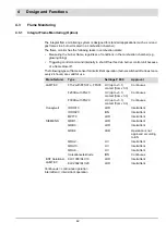
The integral flame monitoring system is designed for standard applications (such as oil and
gas flames in a burner located in a combustion chamber).
The flame monitor has the following tasks in combustion plants:
•
Measuring the burner flame, regardless of conditions in the combustion chamber (e.g.
glowing lining)
•
Triggering control command internally to shut off fuel feed via burner control unit because
of a flame blow-off.
The following types of flame sensor for intermittent operation (burner switched off at least once
every 24 hours) are valid for use.
Continuous = continuous operation
Intermittent = intermittent operation
Manufacturer
Type
Settings P 800
Approval
LAMTEC
F152 with FFS07 o. FFS08
UV (up to v3.1)
contact (from v3.3)
Continuous
F200K with FN20
UV (up to v3.1)
contact (from v3.3)
Continuous
F300K with FN20
UV (up to v3.1)
contact (from v3.3)
Continuous
Honeywell
IRD1010
LDR
Intermittent
IRD1020
ION
Intermittent
MZ770
LDR
Intermittent
SIEMENS
QRB1...
LDR
Intermittent
QRB3...
LDR
Intermittent
QRB4
LDR
Operation is not
approved according
to EN
QRA2...
UV
Intermittent
QRA10...
UV
Intermittent
QRA4...
UV
Intermittent
Ionisationselektrode
ION
Continuous
BST Solutions/
LAMTEC
KLC1000/KLC10
LDR
Intermittent
KLC2002/KLC20
LDR
Intermittent
Summary of Contents for BT300 BurnerTronic
Page 2: ......
Page 25: ...24 3 Product Description Fig 3 9 Temperature derating BT300 for operation 2000 m NHN...
Page 49: ...48 4 Design and Functions Fig 4 20 Oil with pilot burner BT300...
Page 50: ...49 4 Design and Functions Fig 4 21 Oil without pilot burner BT300...
Page 51: ...50 4 Design and Functions Fig 4 22 Gas with pilot burner and leakage test BT300...
Page 52: ...51 4 Design and Functions Fig 4 23 Gas without pilot burner and leakage test BT300...
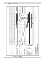
Page 53: ...52 4 Design and Functions Fig 4 24 Oil without pilot burner BT335...
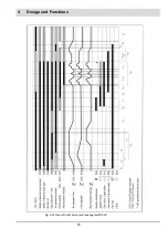
Page 54: ...53 4 Design and Functions Fig 4 25 Gas without pilot burner and leakage test BT335...
Page 59: ...58 4 Design and Functions Fig 4 28 Leakage test process diagram...
Page 98: ...97 6 Operating Control and Displays...
Page 99: ...98 6 Operating Control and Displays...
Page 103: ...102 6 Operating Control and Displays...
Page 105: ...104 6 Operating Control and Displays...
Page 106: ...105 6 Operating Control and Displays...
Page 107: ...106 6 Operating Control and Displays...
Page 109: ...108 6 Operating Control and Displays...
Page 126: ...125 6 Operating Control and Displays 6 3 4 2 Curve Table Fig 6 37 Curve table window...
Page 246: ...242 10 EU Declaration of Conformity 10 EU Declaration of Conformity...
Page 247: ...243 10 EU Declaration of Conformity...

