45
4
Design and Functions
Maintenance
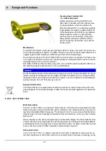
To maintain the detector, just keep the sight glass clean by using a dry cloth. Do not use any
kind of cleaning sprays or liquids. The flame scanner may only be touched at the lateral, cor-
rugated regions when inserting or withdrawing it from the mounting flange.
Due to internal checks of the KLC 20/KLC 2002 no more tests are necessary. The flame scan-
ner’s make circuit/break circuit can be checked easily by holding the flame scanner to an AC
operating light source (no torch or similar).
KLC 20/KLC 2002 switches the flame relay ON – the red LED is permanently ON. After 9 sec.
the switching output is disconnected – the red LED flashes.
NOTICE
Due to the safety function of the disturbance frequency cut-off, a flame simulation is not pos-
sible by means of a simple art source of light. If a flame simulation, such as during the final
inspection of the burner without a real flame is needed, a source of light with a modulating fre-
quency between 60 and 150 cycles per second.
Disposal Information
The flame detector is equipped with electrical and electronic components and must be dis-
posed separate from household waste. Follow the local and actual regulations for waste dis-
posal.
4.3.2.2 KLC 10/KLC 1000
Brief Description
The KLC 10/KLC 1000 is a compact UV flame detector, which has been developed for single
flame combustion which produces little light or radiation in the visible spectrum and has very
low flame modulation/flicker frequency. The design of the UV sensor ensures that the flame
detector does not react to background radiation from hot refractory or from any other infrared
light source.
Flame intensity can be easily recognised by an optical LED display. The flame detector KLC
10/KLC 1000 has been developed to meet the requirements of European Standards EN230
and EN298 for burner management control units which make a ‘no-flame’ check after normal
burner shut down when the flame amplifier is permanently energised.
Safety Instruction
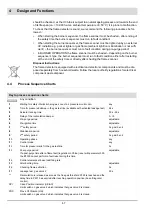
The KLC 10/KLC 1000 is a safety component, and repair or adjustment must never be at-
tempted. Replacement of the flame detector is recommended in all cases of damage, due to
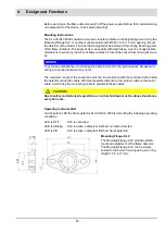
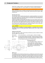
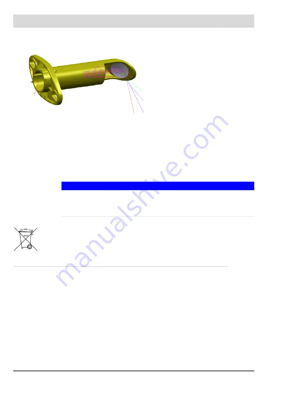
Viewing Angel Adapter KLC
for radial adjustment
Radial adjustment of the KLC2002 to the
flame axis is possible with the optional view-
ing angle adapter, which can replace the
Mounting Flange KLC. An optionally available
angle adapter provides the radial adjustment
to the flame axis of KLC2002 by an optimally
shaped reflector surface. A special flame
scanner type is not necessary. During han-
dling, avoid touching the reflector surface
and, if necessary, clean with a dry, soft and
lint-free cloth.
Summary of Contents for BT300 BurnerTronic
Page 2: ......
Page 25: ...24 3 Product Description Fig 3 9 Temperature derating BT300 for operation 2000 m NHN...
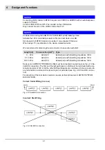
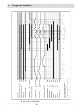
Page 49: ...48 4 Design and Functions Fig 4 20 Oil with pilot burner BT300...
Page 50: ...49 4 Design and Functions Fig 4 21 Oil without pilot burner BT300...
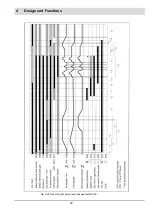
Page 51: ...50 4 Design and Functions Fig 4 22 Gas with pilot burner and leakage test BT300...
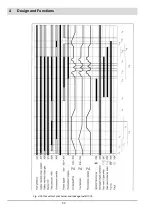
Page 52: ...51 4 Design and Functions Fig 4 23 Gas without pilot burner and leakage test BT300...
Page 53: ...52 4 Design and Functions Fig 4 24 Oil without pilot burner BT335...
Page 54: ...53 4 Design and Functions Fig 4 25 Gas without pilot burner and leakage test BT335...
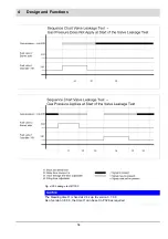
Page 59: ...58 4 Design and Functions Fig 4 28 Leakage test process diagram...
Page 98: ...97 6 Operating Control and Displays...
Page 99: ...98 6 Operating Control and Displays...
Page 103: ...102 6 Operating Control and Displays...
Page 105: ...104 6 Operating Control and Displays...
Page 106: ...105 6 Operating Control and Displays...
Page 107: ...106 6 Operating Control and Displays...
Page 109: ...108 6 Operating Control and Displays...
Page 126: ...125 6 Operating Control and Displays 6 3 4 2 Curve Table Fig 6 37 Curve table window...
Page 246: ...242 10 EU Declaration of Conformity 10 EU Declaration of Conformity...
Page 247: ...243 10 EU Declaration of Conformity...


