47
4
Design and Functions
should be checked, as the UV tube is subject to a natural ageing process and towards the end
of its life span (ca. >10.000 h at an ambient temperature of <50 °C) it is prone to malfunction.
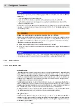
To check that the flame detector is sound, we recommend the following procedures be fol-
lowed:-:
•
When starting the burner sequencer, the flame scanner must be shaded - after ending of
the safety time the burner sequencer must run to fault condition!
•
When starting the burner sequencer, the flame scanner must be lighted up by an external
UV radiation e.g. pocket lighter or gas flame (ambient light/room illumination is not suffi-
cient) – the burner sequencer must run to fault condition during pre-purge period!
•
In BURNER OPERATION the flame scanner must be shaded – depending on the burner
sequencer’s type, the burner sequencer must run to fault condition either after restarting
at the end of the safety time or directly after shading the flame scanner.
Disposal Instructions
The flame detector is equipped with electrical and electronic components and must be dis-
posed separately from household waste. Follow the local authority regulations for electrical
component waste disposal.
4.4
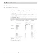
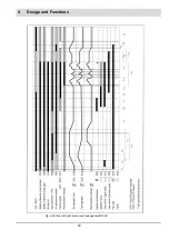
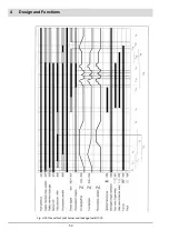
Process Sequence Charts
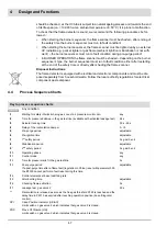
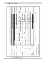
Key to process sequence charts
Any condition
t1
Waiting for safety interlock chain gas, scan of air pressure monitor min.
any
t2
Time for pressure build-up in the gas test line (available with activated leakage test)
2,4 s
t3
Actuator running time
30 s - 60 s
t4
Delay of the recirculation damper
0 - t5
t5
Pre-purge period
adjustable
t6
Pre-ignition time
adjustable
t7
1
st
safety period
3 s gas/5 s oil
t8
Stabilisation period
adjustable
t9’
2
nd
safety period
3 s gas/5 s oil
t10
Operating phase
any
t11
Control mode
any
t12
Time for pressure relief in the gas test line
3 s
t13
Post-purge period
If a post-purge time after a flame fault (regulation in China) is set with parameter 339,
the BT300 cannot perform a fault reset during this time.
adjustable
t14
Control elements at base load/firing rate
t15
After burning time
adjustable
t16
Checking flame extinction
5 s
t17
Leakage test, gas valve 2
30 s
**
Recirculation is released as soon as the flue gas threshold P322 is reached and the
delay time in P331 has expired after reaching operation position (base firing-rate/
control).
CPI
Close Position Indicator (UK/AU)
Limit switch on gas valve 2 which indicates that gas valve 2 is closed.
POC
Prove Of Closure (US)
Limit switch on gas valve 2 which indicates that gas valve 2 is closed.
Summary of Contents for BT300 BurnerTronic
Page 2: ......
Page 25: ...24 3 Product Description Fig 3 9 Temperature derating BT300 for operation 2000 m NHN...
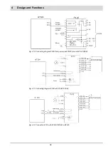
Page 49: ...48 4 Design and Functions Fig 4 20 Oil with pilot burner BT300...
Page 50: ...49 4 Design and Functions Fig 4 21 Oil without pilot burner BT300...
Page 51: ...50 4 Design and Functions Fig 4 22 Gas with pilot burner and leakage test BT300...
Page 52: ...51 4 Design and Functions Fig 4 23 Gas without pilot burner and leakage test BT300...
Page 53: ...52 4 Design and Functions Fig 4 24 Oil without pilot burner BT335...
Page 54: ...53 4 Design and Functions Fig 4 25 Gas without pilot burner and leakage test BT335...
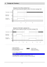
Page 59: ...58 4 Design and Functions Fig 4 28 Leakage test process diagram...
Page 98: ...97 6 Operating Control and Displays...
Page 99: ...98 6 Operating Control and Displays...
Page 103: ...102 6 Operating Control and Displays...
Page 105: ...104 6 Operating Control and Displays...
Page 106: ...105 6 Operating Control and Displays...
Page 107: ...106 6 Operating Control and Displays...
Page 109: ...108 6 Operating Control and Displays...
Page 126: ...125 6 Operating Control and Displays 6 3 4 2 Curve Table Fig 6 37 Curve table window...
Page 246: ...242 10 EU Declaration of Conformity 10 EU Declaration of Conformity...
Page 247: ...243 10 EU Declaration of Conformity...

