57
4
Design and Functions
4.5.2
Leakage Test Process Flow
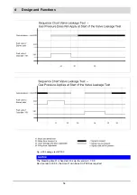
The valve leakage test checks if the main gas valves are sealed. For this purpose the gas
pressure of the supply is analysed.
As valve leakage test section (space between the two main valves) burns empty whenever the
burner is switched off, this part is usually pressureless at start-up (gas pressure > min = 0).
This is checked by BT300. At this point, main gas 1 opens briefly and gas flows into test sec-
tion (gas pressure > min switches from 0 to 1). While main gas 1 valve is open gas pressure
must apply.Otherwise BT300. detects gas deficiency. Gas pressure must remain at least con-
stant during valve leakage test period (2 s + P 311). The valve leakage test is considered com-
plete then.
If leakage test section is not empty at start-up (e.g. resulting from a previous fault shut down),
main gas valve 2 opens first. The leakage test line is then purged (depending on the plant,
either in the combustion chamber or through the roof – for wiring proposition, see chapter
4.5.4 Valve Leakage Test Venting Over the Roof
). During leakage test period section is
checked whether it remains pressureless or not. Apart from that the process is the same as
described above.
The valve leakage test starts after pre-purge has been completed (up to V3.5.0.0).
The valve leakage test starts as soon as the ignition position is reached (from V3.6.0.0).
The pressure monitor for the leakage test line must be connected to the ’Gas pressure > min’
input on plug X05. It also monitors the minimum pressure during operation. If a different min-
imum pressure should be monitored during operation, the pressure monitor must be inserted
into the safety interlock chain gas or into the controller loop (burner ON).
Summary of Contents for BT300 BurnerTronic
Page 2: ......
Page 25: ...24 3 Product Description Fig 3 9 Temperature derating BT300 for operation 2000 m NHN...
Page 49: ...48 4 Design and Functions Fig 4 20 Oil with pilot burner BT300...
Page 50: ...49 4 Design and Functions Fig 4 21 Oil without pilot burner BT300...
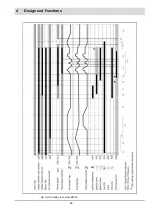
Page 51: ...50 4 Design and Functions Fig 4 22 Gas with pilot burner and leakage test BT300...
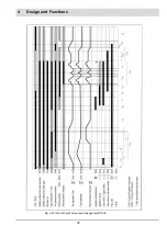
Page 52: ...51 4 Design and Functions Fig 4 23 Gas without pilot burner and leakage test BT300...
Page 53: ...52 4 Design and Functions Fig 4 24 Oil without pilot burner BT335...
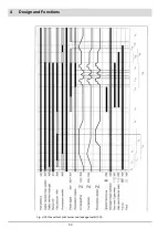
Page 54: ...53 4 Design and Functions Fig 4 25 Gas without pilot burner and leakage test BT335...
Page 59: ...58 4 Design and Functions Fig 4 28 Leakage test process diagram...
Page 98: ...97 6 Operating Control and Displays...
Page 99: ...98 6 Operating Control and Displays...
Page 103: ...102 6 Operating Control and Displays...
Page 105: ...104 6 Operating Control and Displays...
Page 106: ...105 6 Operating Control and Displays...
Page 107: ...106 6 Operating Control and Displays...
Page 109: ...108 6 Operating Control and Displays...
Page 126: ...125 6 Operating Control and Displays 6 3 4 2 Curve Table Fig 6 37 Curve table window...
Page 246: ...242 10 EU Declaration of Conformity 10 EU Declaration of Conformity...
Page 247: ...243 10 EU Declaration of Conformity...

