59
4
Design and Functions
4.5.3
Reaction on Gas Deficiency
If main gas 1 valve is open and the pressure drops below the minimum pressure, gas deficien-
cy is detected. This causes a safety shut down and fault indication H611. Further reactions are
depending on the settings in P301 (automatic restart).
If P301 = 1 (no automatic restart) BT300 remains permanently in a fault position and must be
unlocked if gas pressure returns.
If P301 = 0 (automatic restart according to TRD) or P301 = 2 (automatic restart according to
EN676), BT300 waits until the delay in P328 has elapsed and tries to start again then.
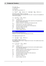
If gas deficiency is detected once more the delay will be doubled with every further attempt to
restart until a delay one hour is reached.
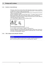
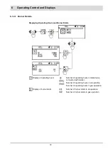
The remaining delay is displayed in the User Interface UI300.
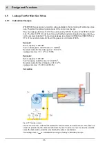
Fig. 4-29 Indication of fault H611 gas deficiency with restart
The time until the next start attempt is displayed in the bottom line.
During the waiting time, the red fault lamp on the UI300 lights up permanently. Pressing the
reset button cancels the waiting time and the BT300 immediately makes a new start attempt.
The number of start attempts is unlimited.
4.5.4
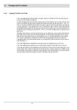
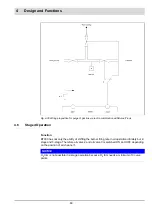
Valve Leakage Test Venting Over the Roof
NOTICE
Consider diameter of gas line in the roof purge. For purge, plug X02 is activated for 3 s.
Make sure that this period is sufficient even for smallest purge line diameter!
Summary of Contents for BT300 BurnerTronic
Page 2: ......
Page 25: ...24 3 Product Description Fig 3 9 Temperature derating BT300 for operation 2000 m NHN...
Page 49: ...48 4 Design and Functions Fig 4 20 Oil with pilot burner BT300...
Page 50: ...49 4 Design and Functions Fig 4 21 Oil without pilot burner BT300...
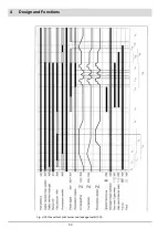
Page 51: ...50 4 Design and Functions Fig 4 22 Gas with pilot burner and leakage test BT300...
Page 52: ...51 4 Design and Functions Fig 4 23 Gas without pilot burner and leakage test BT300...
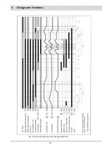
Page 53: ...52 4 Design and Functions Fig 4 24 Oil without pilot burner BT335...
Page 54: ...53 4 Design and Functions Fig 4 25 Gas without pilot burner and leakage test BT335...
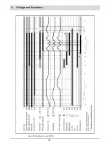
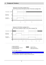
Page 59: ...58 4 Design and Functions Fig 4 28 Leakage test process diagram...
Page 98: ...97 6 Operating Control and Displays...
Page 99: ...98 6 Operating Control and Displays...
Page 103: ...102 6 Operating Control and Displays...
Page 105: ...104 6 Operating Control and Displays...
Page 106: ...105 6 Operating Control and Displays...
Page 107: ...106 6 Operating Control and Displays...
Page 109: ...108 6 Operating Control and Displays...
Page 126: ...125 6 Operating Control and Displays 6 3 4 2 Curve Table Fig 6 37 Curve table window...
Page 246: ...242 10 EU Declaration of Conformity 10 EU Declaration of Conformity...
Page 247: ...243 10 EU Declaration of Conformity...

